




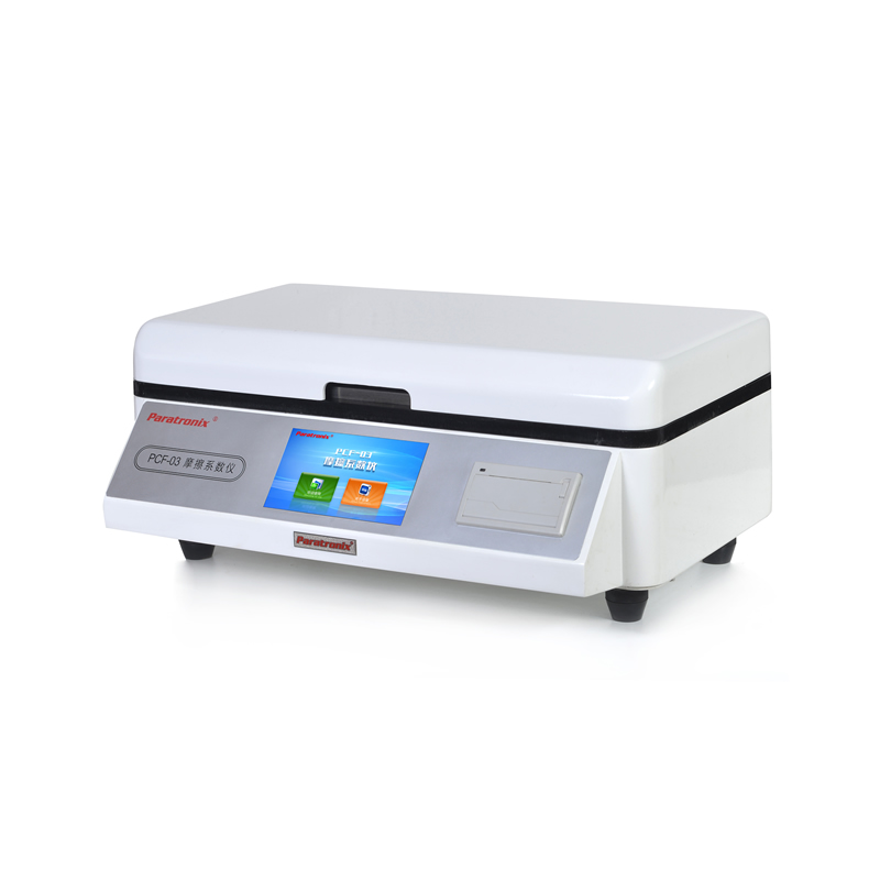
What A Friction Coefficient Tester Measures
A Friction Coefficient Tester measures the resistance generated when one surface moves against another under a defined normal load. For plastic film and sheeting, the instrument typically pulls a sled across a horizontal specimen while recording force. The coefficient of friction, commonly abbreviated COF, is the measured frictional force divided by the normal force. It is dimensionless, so meaningful comparisons depend on clearly defined materials, contact conditions, and test procedures rather than units alone.
Static COF describes resistance at the onset of movement, while kinetic COF describes resistance during continued sliding. A high initial peak can indicate a tendency for surfaces to resist starting, even when subsequent sliding is relatively easy. These measurements help explain feeding, stacking, and opening behavior, but they do not independently predict every production outcome. Roller geometry, line speed, electrostatic effects, web tension, and environmental conditions can also influence how packaging materials behave in service.
Typical users include film extruders, flexible packaging converters, coating developers, packaging buyers, and quality control laboratories. They use friction measurements to compare formulations, monitor surface treatments, investigate handling complaints, and qualify incoming materials. Film against film and film against metal answer different questions, so the contact pair must match the intended decision. A purchasing specification that states only a COF limit leaves important uncertainties about the method and the surface combination used to establish acceptance.
How ASTM D1894 And ISO 8295 Compare
ASTM D1894 addresses static and kinetic coefficients of friction of plastic film and sheeting. ISO 8295 addresses determination of coefficients of friction for plastics film and sheeting. Both establish controlled sliding measurements, but their shared purpose does not make their results automatically interchangeable. Laboratories should identify the required standard, its edition, and any customer specification before selecting instrument settings. The applicable published document remains the authority for apparatus requirements, specimen preparation, conditioning, execution, and reporting.
Differences in prescribed test conditions can affect the measured result. Commonly cited nominal test speeds are 150 mm/min for ASTM D1894 and 100 mm/min for ISO 8295; laboratories must verify the requirements and permitted variations in their applicable editions. Sled characteristics, specimen mounting, contact time, and evaluation procedures also deserve review. Changing only the speed setting is insufficient evidence that an established method has been fully converted from one standard to the other.
Choose the standard specified by the customer, material agreement, or established quality system. When both are requested, create separate controlled methods and evaluate representative materials under each. Do not apply a universal conversion factor between the results without supporting evidence. For a paratronix PCF-03 Coefficient of Friction Tester evaluation, request a demonstration against the selected standard and edition. Product naming alone does not establish conformity, and instrument capability should be checked against each relevant apparatus and procedural requirement.
Measurement Principles And Main Equipment Types
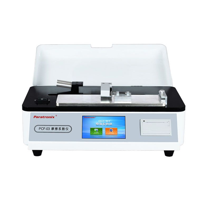
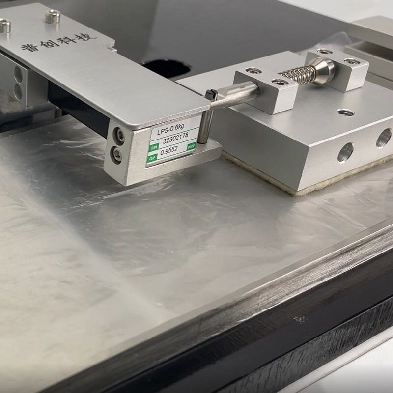
In a horizontal sled system, a force sensor records the resistance transmitted through the pulling connection while a drive produces relative movement. The software derives static COF from the appropriate starting response and kinetic COF from the specified sliding interval. Accurate interpretation requires the normal force to be correctly established and the force signal to remain within a suitable measurement range. Vibration, misalignment, connection elasticity, and abrupt acceleration can distort the initial peak or introduce fluctuations during sliding.
Equipment can be grouped into dedicated horizontal sled testers, universal testing machines fitted with friction accessories, and application specific friction systems. Dedicated instruments can simplify routine film testing, while a multipurpose frame may support several mechanical tests when equipped appropriately. Inclined plane devices also assess friction behavior, but their geometry and procedure differ from horizontal sled methods. Buyers should therefore select an instrument around the required standard and application rather than treating all friction measurement devices as equivalent.
Another distinction concerns what moves: some arrangements pull the sled over a stationary surface, while others move the supporting surface relative to the sled. Suitability depends on the standard and the complete apparatus design. Automated data capture can improve traceability, but useful software must expose the force curve, calculation interval, units, and method settings. A single displayed COF number provides limited diagnostic value when a laboratory needs to investigate stick-slip behavior, an abnormal peak, or inconsistent specimen mounting.
Specimen Preparation And Reliable Quality Control
Begin with a sampling plan that represents the roll, batch, or production condition being evaluated. Record specimen identity, film side, machine direction or transverse direction where relevant, and the opposing contact material. Cut specimens cleanly and avoid stretching, wrinkling, or touching the test area. Mount them using the procedure required by the method. If a film has different inner and outer surfaces, test the intended pairing explicitly because reversing the contact surfaces can change the result substantially.
Condition specimens according to the applicable standard and document the test environment. Temperature, humidity, storage history, and time since manufacture may influence surface behavior, particularly in films containing migrating slip additives. Keep the interval between surface contact and movement controlled where required. Inspect and clean the apparatus using an approved procedure that avoids residue or surface damage. Use fresh contact areas or specimens as prescribed; repeated sliding can change the interface and undermine comparisons between nominally identical tests.
A reliable workflow includes force verification, speed checks, inspection of the sled and contact surface, and review of the full force trace. Follow the required replicate count and reporting rules, retaining individual results alongside summary statistics where useful. Investigate unusual variation before assigning a batch decision. Reports should identify the standard and edition, material pairing, conditioning, settings, and deviations. Reference materials or retained control films can support routine monitoring, although their stability must be established rather than assumed indefinitely.
Selecting Equipment And Evaluating Paratronix
Start a Friction Coefficient Tester purchase with a written user requirement covering materials, expected friction range, standards, sample throughput, and reporting needs. Evaluate force resolution together with accuracy, calibration uncertainty, and the expected operating range; a high resolution display alone does not establish measurement quality. Confirm the available speed settings, travel, sled configuration, specimen fixtures, and installation conditions. Request evidence that the proposed setup can accommodate thin, flexible, or coated samples without introducing avoidable mounting problems.
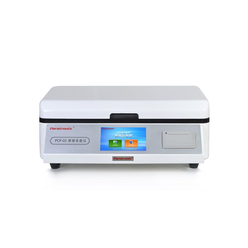
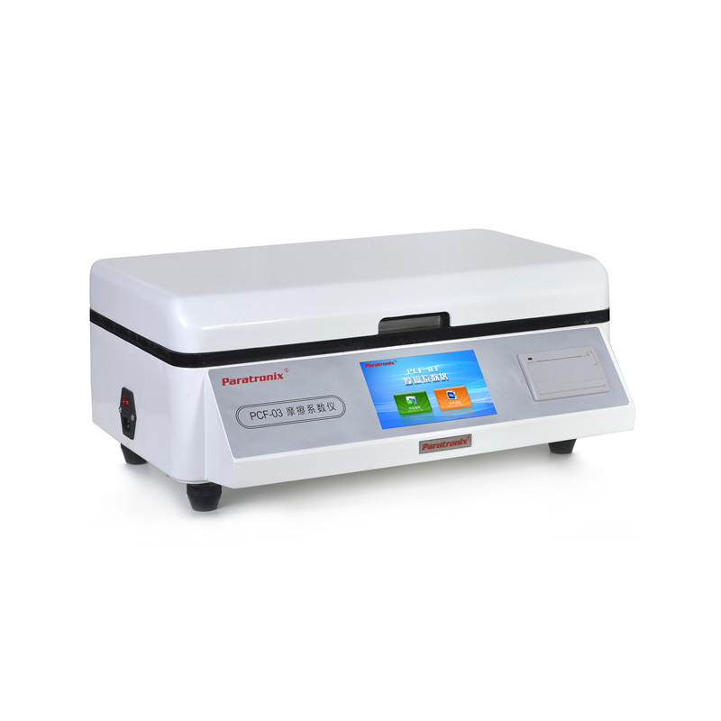
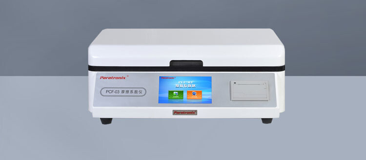
The paratronix PCF-03 Coefficient of Friction Tester is a relevant product to assess for this application. Ask paratronix to provide current specifications, the supported method configurations, a representative test report, and a demonstration using your own material pairs. Evaluate repeatability across operators and days when the purchasing decision depends on narrow acceptance limits. Confirm which accessories, calibration documents, software functions, installation services, and training are included in the quotation instead of assuming that every requirement is part of the standard supply.
Paratronix lists a broader testing equipment portfolio covering water vapor permeability, leakage, torque, air permeability, and medical packaging physical performance. This breadth may be useful when discussing several laboratory needs with one supplier, but each instrument requires its own technical assessment. The supplied business registration identifier, Unified Social Credit Code 91370105689842696E, supports supplier identity checks; it is not a product performance certification. Procurement teams should assess documented capabilities, service arrangements, and contractual acceptance criteria separately from business registration information.
Applications Acceptance Limits And Ownership Costs
In packaging operations, friction testing can help investigate poor feeding, unstable stacks, difficult bag opening, or changes after coating and printing. These are typical application scenarios rather than documented paratronix customer cases. A useful investigation compares affected and acceptable material under the same controlled method, then relates the findings to production observations. For medical packaging, COF may support handling assessments, but it does not replace tests for seal strength, package integrity, barrier performance, or other applicable packaging requirements.
Acceptance limits should come from functional trials, customer agreements, and demonstrated process capability. There is no single ideal COF value for every packaging film: easier sliding may assist one operation while reducing stability in another. Establish separate limits where material sides, contact pairs, or test standards differ. During supplier qualification, agree on sample age, conditioning, test settings, and reporting conventions. Shared procedures and interlaboratory comparisons can reduce disputes caused by testing differences rather than actual changes in material performance.
Total ownership cost includes the instrument, accessories, calibration, operator training, software support, maintenance, and labor per accepted result. Consider sample preparation time and the cost of repeat testing when comparing quotations. Estimate return on investment using your own records for troubleshooting time, external laboratory spending, and avoidable material losses. Require evidence before assigning savings to a new instrument. Service response, replacement part availability, and access to method support can materially affect laboratory continuity over the equipment's working life.
Maintenance Digital Reporting And Future Priorities
Set maintenance and calibration intervals according to usage, manufacturer guidance, measurement risk, and observed stability. Inspect contact surfaces and pulling components before use, and perform additional verification after relocation, repair, overload, or unexplained changes in results. Maintain records of adjustments and investigate drift before releasing affected data. Where results support contractual acceptance, define how potentially affected batches will be reviewed. A fixed annual service date alone cannot demonstrate that an instrument remained suitable throughout the intervening period.
Current development priorities include better data traceability, controlled method templates, and easier transfer of results into laboratory information systems. Evaluate these features against actual workflow needs and verify whether they are available on the proposed instrument. New film formulations, recycled content, and coating changes also increase the value of systematic friction characterization. They do not justify universal predictions: surface behavior depends on the complete formulation and processing history, so representative conditioning and production correlation remain essential.
Before requesting a quotation, prepare a concise application brief identifying ASTM D1894 or ISO 8295, the required edition, specimen types, contact pairings, throughput, and acceptance criteria. Share representative samples with paratronix and request a PCF-03 configuration proposal supported by a documented demonstration. Review the resulting curves, method settings, and service scope with laboratory and purchasing personnel. This creates a concrete basis for deciding whether the proposed Friction Coefficient Tester meets your quality control requirements and commercial expectations.
 What Is a Friction Coefficient Tester and Where Is It Used in Quality Control?Friction Coefficient Tester: learn how static and kinetic COF testing improves packaging quality, prevents feeding issues, and supports reliable production.
 ASTM D1894 vs. ISO 8295: Which Friction Test Standard Should You Use?Friction Coefficient Tester guide: compare ASTM D1894 and ISO 8295, control COF variables, and choose the right standard for reliable packaging performance.
Search by Keywords