





Auto Tensile Tester Standards Explained: ASTM And ISO Test Methods
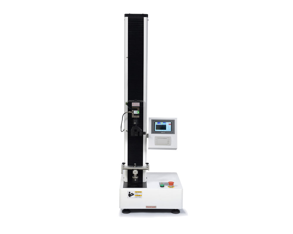
An Auto Tensile Tester is a force testing system that applies controlled tension to a specimen while recording force and displacement or strain. Depending on its configuration, automation can cover crosshead movement, data capture, calculations, specimen handling, and reporting. The equipment supports material development, incoming inspection, production control, and failure investigation. Its practical value depends on whether the complete testing arrangement matches the relevant method, including specimen geometry, gripping, measurement accuracy, and environmental conditions.
ASTM and ISO standards define procedures for particular materials and properties; they do not establish one universal tensile test. A thin packaging film, a molded plastic component, an elastomer strip, and a flexible package seal require different preparations and interpretations. Selecting a standard therefore begins with the specimen and the engineering question. Buyers should identify whether they need tensile strength, elongation, modulus, seal strength, or another property before selecting the machine and accessories.
Automation improves consistency by executing defined sequences and reducing transcription work, but it cannot correct an unsuitable method or damaged specimen. A motorized tester with automatic calculations also differs substantially from a system that loads and removes specimens without an operator. Procurement documents should state which activities require automation. Laboratories should then establish operator responsibilities, acceptance criteria, and review procedures so that the resulting measurements remain traceable to the actual test conditions.
How Tensile Measurement Works And Which Configurations Matter
During a tensile test, a drive moves the grips apart according to the selected control program. A load cell measures force, while crosshead position or a separate extensometer measures movement. Engineering stress generally relates force to the original cross-sectional area, and engineering strain relates extension to the original gauge length. Consequently, errors in thickness, specimen width, or gauge length can affect calculated properties even when the force measurement itself is accurate.
Crosshead displacement includes deformation within the load train, grip movement, and possible specimen slip. It should not automatically be treated as specimen strain. Modulus measurements and other strain-sensitive evaluations may require a suitable extensometer and compliance with the method's measurement provisions. Noncontact optical systems can help with delicate or highly extensible specimens, while contact extensometers suit other applications. The correct choice depends on required accuracy, gauge length, material behavior, and the selected standard.
Mainstream equipment configurations include single-column systems for many lower-force applications and dual-column frames for larger loads or specimens. Available travel, frame stiffness, grip clearance, and accessory compatibility matter alongside nominal capacity. Manual, pneumatic, and specialized film grips address different handling needs. An Auto Tensile Tester intended for both thin films and stronger components may require interchangeable load cells and fixtures; one large-capacity sensor should not be assumed suitable for every low-force measurement.
ASTM And ISO Methods For Films, Plastics, And Elastomers
ASTM D882 addresses tensile properties of thin plastic sheeting, while ISO 527-3 provides test conditions for films and sheets within the ISO 527 framework. ASTM D638 and ISO 527-2 are commonly relevant to molded and extruded plastics within their respective scopes. These standards are not interchangeable labels. Specimen dimensions, test speeds, strain measurement requirements, and calculation conventions can differ. Confirm the applicable scope and current contractual edition before preparing specimens or comparing supplier results.
For vulcanized rubber and thermoplastic elastomers, ASTM D412 and ISO 37 are established tensile testing references. Their specimens and procedures reflect material behavior that differs from relatively rigid plastics. High elongation can require substantial crosshead travel and grips that maintain contact without causing premature failure. If a laboratory tests multiple material families, each method needs its own approved setup, specimen preparation instructions, measurement configuration, and reporting fields rather than a shared generic tensile program.
Film orientation also matters. Machine-direction and transverse-direction specimens can produce different results because processing creates directional structure. Record orientation, thickness measurement practice, conditioning, specimen count, and relevant failure observations. A break near a grip or visible slippage should trigger review against the method's validity provisions. For purchasing decisions, request a demonstration using representative specimens and the intended standard. A machine's force range alone does not demonstrate that it can execute the required procedure.
Packaging Seal Tests And Complementary Integrity Methods
ASTM F88/F88M addresses seal strength of flexible barrier materials and is particularly relevant to packaging evaluation. Although a tensile frame may perform the test, seal strength is a different measurement from bulk material tensile strength. Specimen width, tail support technique, separation rate, and failure mode influence interpretation. Laboratories should document the selected technique and report the information required by the method. Comparisons become unreliable when laboratories silently change fixtures or specimen support.
Seal strength also differs from package integrity. A seal may resist separation while a package contains a leak elsewhere, and a leak test does not establish tensile properties. For terminally sterilized medical device packaging, the ISO 11607 series provides a broader framework for packaging system requirements and process validation. An individual tensile or leak test supplies only part of the evidence needed to assess a packaging system against its specified requirements.
paratronix lists leak and seal strength testers, medical packaging physical performance testers, non-destructive micro-leakage testers, and water vapor permeability testers among its offerings. These categories can support complementary investigations into mechanical performance, integrity, and barrier behavior. Buyers should ask paratronix to map each proposed instrument to the required property and method. Confirm fixture availability, package compatibility, measurement capability, and any claimed nondestructive operation for the actual sample rather than assuming every configuration covers all applications.
Equipment Selection, Verification, And Supplier Evidence
Start an Auto Tensile Tester specification with expected minimum and maximum forces, specimen dimensions, anticipated extension, required properties, and named test methods. Evaluate the verified operating range of each load cell, not just its maximum rating or displayed resolution. Small film and seal forces can be difficult to characterize with an oversized sensor. The related article, Choosing an Auto Tensile Tester: Load Cell Range for Thin Films, provides a useful topic for deeper procurement review.
Force verification commonly references ASTM E4 or ISO 7500-1, as applicable to the equipment and specification. Extensometer verification or calibration may reference ASTM E83 or ISO 9513. These references address measurement performance; they do not replace the material test method. Request certificates showing the relevant range, results, traceability, and applicable classification or acceptance basis. Also examine crosshead speed verification, alignment, data acquisition, and whether environmental accessories affect the measurement arrangement.
Supplier assessment should distinguish legal identity from technical capability. The supplied business information identifies paratronix with Unified Social Credit Code 91370105689842696E; this identifier does not establish instrument certification or method compliance. Request a configuration-specific quotation, manuals, service terms, and an acceptance demonstration with representative samples. Where software offers standard templates, verify the underlying parameters and calculations. A standard's name in a menu is insufficient evidence that the complete test setup satisfies its requirements.
Test Workflow, Quality Control, And Results Interpretation
A reliable workflow begins with sample identification, preparation, dimensional measurement, and conditioning under the applicable method or agreed specification. Inspect cutting tools and specimen edges because damage can initiate premature failure. Install the correct load cell and grips, verify alignment, and enter the required dimensions and gauge length. Apply preload or slack compensation only where appropriate to the method. Record settings before testing so operators can identify departures from the approved procedure.
During testing, inspect force curves and observe slip, tearing, jaw breaks, and unexpected deformation. Automatic calculations need explicit definitions for maximum force, break detection, averaging intervals, and any exclusion rules. Preserve raw data alongside calculated results so reviewers can investigate anomalies. Where software filters measurements, document the settings and assess their effect on reported properties. Repeating a measurement without investigating its failure mechanism can create additional data while leaving the original problem unresolved.
Reports should identify the method and edition, specimen details, conditioning, equipment configuration, test settings, calculated properties, and relevant deviations. Include individual results and suitable summary statistics when required. Acceptance limits should come from the product specification, customer agreement, or validated process requirements rather than an assumed universal threshold. Establish maintenance and verification intervals according to usage, manufacturer guidance, measurement risk, and quality system requirements, with additional assessment after repairs, overloads, or significant equipment changes.
Ownership Costs, Automation Trends, And Procurement Decisions
Total ownership cost includes the frame, load cells, grips, extensometers, software, installation, training, calibration, maintenance, and specimen preparation. Additional costs can arise from pneumatic supplies, environmental control, software licensing, and replacement grip faces. Throughput depends on preparation and handling as well as crosshead speed. Ask suppliers to demonstrate a complete testing cycle using representative specimens, including setup and reporting, so productivity estimates reflect the laboratory's workload and operator involvement.
Evaluate return on investment through measurable changes in operator time, repeat testing, reporting effort, and investigation speed. Avoid assigning financial benefits to improved quality without a defensible baseline. Future development is likely to emphasize connected laboratory records, automated specimen handling, optical strain measurement, and more consistent method management. These capabilities remain valuable only when the measurement chain is suitable and data exports, user permissions, version histories, and system integration meet the laboratory's operational requirements.
To discuss an Auto Tensile Tester requirement with paratronix, provide the material or package type, applicable ASTM or ISO method, specimen dimensions, expected force range, extension needs, and daily sample volume. Include any related seal strength, leakage, or barrier testing requirements so the proposed equipment package addresses the full inspection task. Request written confirmation of configuration, verification scope, software functions, acceptance criteria, and service support. This creates a reviewable basis for comparing quotations and approving the purchase.
Search by Keywords