




Recent Posts
 Bone Screw Insertion Testing vs. Pullout Testing: What Each RevealsOct 13, 2026
 ASTM F543 Torsion Testing: Fixture and Data Requirements for Bone ScrewsOct 13, 2026
 Choosing an Auto Tensile Tester: Load Cell Range for Thin FilmsOct 13, 2026
 ASTM F2029 Heat Seal Tester Setup: Temperature, Pressure, and Dwell TimeOct 13, 2026
 ASTM D642 and ISO 12048: Requirements for Package Compression TestingOct 12, 2026
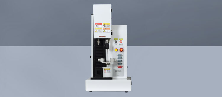

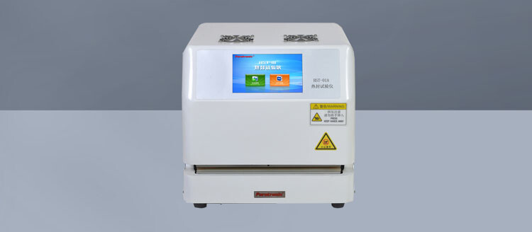
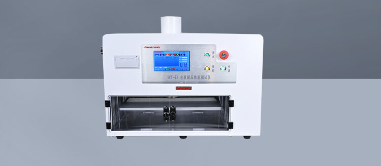
A suitable load cell for thin-film testing must cover the highest credible specimen force while measuring the lower forces that matter to your acceptance criteria. For an Auto Tensile Tester, that usually means choosing the smallest capacity that provides adequate operating headroom and a verified measurement range covering the test. Selecting a higher capacity for flexibility can be reasonable, but only if its low-force performance is demonstrated.
The selection starts with two boundaries: the greatest force the specimen could generate and the lowest force you need to measure reliably. Peak force determines capacity; the lower boundary determines whether the instrument can support measurements such as yield, specified-strain force, or the early part of the tensile curve. A load cell can be adequate for breaking-force measurements yet unsuitable for another result obtained from the same specimen.
Build the force estimate around the specimen you will actually test.
Film thickness alone does not establish the required load cell range. Force depends on the specimen’s cross-sectional area and tensile response under the chosen test conditions. A thin but wide strip may generate more force than a thicker, narrower specimen. Orientation also matters: machine-direction and transverse-direction specimens can behave differently, so estimating capacity from only one direction can leave part of the test program uncovered.
Where a credible tensile-strength estimate is available, a useful starting calculation is:
Estimated peak force = tensile strength × specimen width × specimen thickness.
With tensile strength expressed in MPa, equivalent to N/mm², and width and thickness in millimetres, the resulting force is in newtons. The estimate assumes the strength value represents the material and test conditions in question. It is a screening calculation, not a substitute for representative force data.
For illustration, suppose a film has an assumed tensile strength of 40 MPa, a test width of 15 mm, and a thickness of 0.025 mm. Its cross-sectional area is 0.375 mm², giving an estimated peak force of 15 N. These are hypothetical inputs, not a specification for a particular packaging film. They show why a machine’s large frame capacity says little about the load cell needed for an individual thin-film method.
For laminates and high-barrier structures, using the strength of one constituent layer with the total thickness can produce a misleading estimate. The complete structure may show sequential layer failure, delamination, or a force peak governed by its combined response. Existing force curves from comparable specimens are more useful than a calculation built from unrelated material datasheets. If only approximate properties are available, keep the estimate provisional until representative specimens have been tested.
Build the upper boundary from the strongest plausible specimen within the intended scope. Consider permitted thickness variation, specimen width, both test directions, material grades, and relevant conditioning. A nominal sample from one production batch provides limited evidence for equipment expected to support a broader quality-control program. Equally, hypothetical future materials should not automatically dictate a much larger load cell when an interchangeable cell could cover them later.
Specimen geometry must remain consistent with the test method. Narrowing a strip solely to fit a smaller load cell changes the test configuration and may affect comparability, particularly where edge damage or specimen preparation influences failure. Establish the required geometry first, then choose the measurement range around it.
Find the lowest force that carries a decision.
Breaking force is often the easiest measurement to accommodate because it occurs near the upper end of the specimen’s force curve. Other reported properties can depend on substantially lower forces. If the evaluation includes force at a specified elongation, an initial slope, or a small yield feature, the relevant measurement range extends well below the maximum load.
This distinction should be settled before reviewing equipment specifications. A laboratory reporting only maximum force and elongation at break may have different force-measurement requirements from a development team comparing the early tensile response of flexible films. The latter also needs suitable strain measurement and control of specimen seating and compliance; choosing a sensitive load cell alone does not establish reliable modulus measurement.
Ask the supplier to identify the verified lower limit of the proposed force-measurement range. A statement such as “high accuracy” is insufficient without the applicable range and the basis of the error specification. Accuracy expressed as a percentage of the reading behaves differently from accuracy expressed as a percentage of full scale. Specifications may also combine a reading-based term with a fixed term, which becomes more significant as force decreases.
A hypothetical example makes the distinction clear. If a 500 N cell had an error limit of ±0.5% of full scale, that term alone would equal ±2.5 N. At a measured force of 5 N, it would be large relative to the result. A specification of ±0.5% of reading would imply a different error allowance, but its validity would still depend on the stated measurement range and any additional terms. The wording and range restrictions matter as much as the percentage.
Display resolution provides little assurance on its own. An instrument may display several decimal places while noise, drift, or measurement uncertainty prevents those digits from supporting meaningful comparisons. Request calibration results or verification evidence near the lowest decision-relevant force, rather than relying entirely on points near rated capacity. The evidence should apply to the installed measurement chain, including the load cell, electronics, and configured range.
Low-force performance also depends on how the instrument behaves during a test. Grip weight can consume physical capacity even when the displayed force has been tared to zero. Temperature changes, alignment, cable movement, and unstable zero readings can affect small measurements. Ask how the proposed arrangement performs with the actual grips installed and after the preparation steps used in routine operation.
Allow headroom for real operating conditions.
A capacity equal to the predicted maximum specimen force leaves little room for material variability or errors in the estimate. The required headroom should reflect the confidence in the force data, the spread of materials tested, and the consequences of exceeding the measurement range. There is no single percentage that makes every thin-film application adequately protected.
For example, if representative specimens generate peaks between 12 and 18 N, a 20 N cell deserves careful scrutiny because it leaves little room above the observed maximum. A 50 N cell may be a practical candidate, provided its verified performance covers the lower forces used in the analysis. This is an illustrative selection comparison, not a universal recommendation. The decision still depends on allowable specimen variation, installed fixtures, and the cell’s operating limits.
Keep rated measuring capacity separate from overload tolerance. A supplier may quote a safe overload limit above the rated range, but that does not extend the range over which measurement accuracy is established. Mechanical survival beyond capacity also does not justify routine operation there. Understand whether an overload could require inspection or recalibration before subsequent results can be trusted.
Automatic operation introduces additional considerations. Preload routines, rapid approach movements, incorrect grip positioning, and travel after specimen rupture can create conditions that differ from the intended tensile pull. Software force limits help, but their effectiveness depends on acquisition, controller response, and stopping behaviour. They should not be treated as a guarantee that a sensitive cell cannot experience a transient overload.
Assess protection as part of the complete machine configuration. The supplier should explain how force limits, travel limits, approach speed, and fixture clearances work together. Where a small cell is proposed, consider the practical consequences of specimen-loading mistakes or accidental contact between fixtures. Useful protection reduces exposure to these events while preserving the measurement performance required for the test.
Decide whether one cell can serve the full material range.
A single load cell is convenient when the strongest and weakest specimens fall within its verified measurement range. It reduces changeovers and simplifies configuration control. The compromise becomes less attractive when a laboratory tests both very low-force films and substantially stronger or wider structures. A cell sized for the strongest specimen may offer insufficient evidence of performance at the lower end.
Interchangeable cells can resolve that mismatch, provided the machine supports them properly. Evaluate the usable force range of each proposed cell, the compatibility of grips and adapters, and the calibration requirements after a change. Check whether the system identifies the installed cell and applies appropriate limits automatically. Manual configuration can be workable, but it introduces another step that operators must complete correctly.
Automation should make the measurement configuration traceable. The test record should identify the cell and relevant method settings, particularly where results from different ranges are compared. A saved recipe associated with the wrong cell can undermine an otherwise suitable equipment choice. For a laboratory with frequent material changes, configuration checks may be as important operationally as the speed of the physical changeover.
Before comparing quotations, prepare a short application brief containing:
- The required specimen widths, thickness range, materials, and test directions.
- Representative peak forces, including the strongest expected condition and the basis for the estimate.
- The lowest force used to calculate or judge a reported result.
- The test speeds, preload settings, grips, and conditioning relevant to the method.
- The acceptable force error or uncertainty at the points that influence acceptance decisions.
Use that brief to request a proposed capacity and supporting measurement evidence. A quotation stating only frame capacity, load cell capacity, and a headline accuracy value leaves the central selection question unanswered. The supplier should be able to connect the proposed range to your specimens and explain any limitations at the lower end.
A demonstration with representative films is especially useful when low-force measurements drive the decision. Include both the weakest material and a specimen near the upper force boundary. Examine the force curve, zero stability, and any signs of clipping or excessive filtering. Repeat specimens can reveal operational variation, although repeatability alone does not establish accuracy: a system can produce closely grouped readings while retaining a systematic error.
Interpret those results alongside specimen behaviour. Grip slip, edge damage, misalignment, or failure at the grip can invalidate comparisons between candidate systems. Sampling rate and filtering can also change how short-duration force features appear. Resolve these issues before attributing every difference in the reported peak or curve shape to load cell capacity.
The final choice should be defensible in a few concrete statements: the strongest expected specimen fits within the operating range with justified headroom; the lowest important force lies within a demonstrated measurement range; and the installed grips, settings, and protection support both conditions. If one cell cannot satisfy those statements, specify an additional range. That gives the Auto Tensile Tester a defined measurement envelope that technical evaluators can assess before purchase and maintain as the film test program changes.
Leave A Reply
Search by Keywords