




Recent Posts
 Bone Screw Insertion Testing vs. Pullout Testing: What Each RevealsOct 13, 2026
 ASTM F543 Torsion Testing: Fixture and Data Requirements for Bone ScrewsOct 13, 2026
 Choosing an Auto Tensile Tester: Load Cell Range for Thin FilmsOct 13, 2026
 ASTM F2029 Heat Seal Tester Setup: Temperature, Pressure, and Dwell TimeOct 13, 2026
 ASTM D642 and ISO 12048: Requirements for Package Compression TestingOct 12, 2026
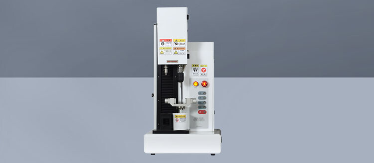

ASTM F543 torsion testing requires a controlled load path through the bone screw and a torque–angle record that supports the specified calculations. A Bone Screw Torsion Tester must therefore be evaluated together with its fixtures, drive interface, angular measurement, and data processing. Adequate torque capacity alone does not establish that a system can produce valid results.
The first distinction is between measuring a screw’s torsional properties and measuring the torque required to insert it into a material. Both involve rotation, but they answer different questions. Torsional testing loads a restrained screw to characterize its mechanical response; insertion testing includes thread interaction with the receiving material. Confusing these configurations produces results that cannot be interpreted against the same requirements.
Define the applicable method before specifying equipment
ASTM F543 addresses metallic medical bone screws and includes several test methods. For torsional properties, the relevant method is Annex A1. The applicable edition must govern fixture geometry, specimen engagement, rotational conditions, endpoint definitions, and calculations. A general statement that equipment “supports ASTM F543” leaves these details unresolved.
Separate the requirements taken directly from the standard from additional laboratory controls. Specified test conditions and result definitions belong in the method. Fixture identification, alignment verification, raw-data retention, and photographs of unusual failures are useful supporting controls, but they should not be presented as mandatory ASTM provisions unless the applicable text requires them.
Screw design also affects applicability. A cannulated shaft, unusual drive recess, variable thread geometry, or short available gripping length can complicate the standard arrangement. Any necessary adaptation should be identified before testing, with its effect on comparability assessed and documented. An adapted procedure should not be reported as unqualified conformity to the standard.
The fixture determines where torsion actually occurs
The load path generally runs from the rotating drive, through the screw head and exposed screw section, into the restraint. The intended test section must remain free to twist while the restrained portion stays secure. If that boundary moves during loading, both the mechanical response and the recorded angle change.
Restraint position is especially consequential. Increasing the exposed length generally increases angular compliance, even when the shaft’s material and cross-section remain unchanged. Consequently, two screws can show different angular displacement at a similar torque because their tested lengths differ. The engagement length and exposed geometry must follow the applicable method and remain traceable in the test record.
A chuck that prevents visible rotation can still damage the specimen. Concentrated jaw pressure can indent threads, distort a thin wall, or introduce a stress concentration near the restraint boundary. For cannulated screws, excessive radial compression is particularly concerning because the remaining wall carries the torsional load. Gripping pressure should secure the specimen without creating an unintended failure origin.
Matched inserts or collets can improve support and positioning, provided they preserve the required restraint arrangement. Generic jaws require closer attention to contact location and repeatability. Neither fixture style is inherently sufficient: the relevant question is whether it holds the actual screw geometry consistently without altering the section being evaluated.
Drive engagement and axial alignment
The driver must fit the recess and remain engaged throughout loading. A worn or poorly matched bit introduces clearance, uneven contact, and a greater chance of recess damage. A sudden torque drop caused by driver disengagement is not equivalent to fracture of the screw shaft, even though both events can terminate the curve.
Engagement depth and axial seating deserve explicit control. Insufficient seating concentrates contact near the recess entrance. Excessive axial force can add an unintended load and affect contact behavior. Any axial force or restraint used to maintain engagement must be consistent with the applicable method and recorded when it affects interpretation.
Alignment concerns the screw axis, driver axis, and restrained section. Offset between them introduces bending alongside torsion. Visible runout during rotation is a useful warning, but an absence of obvious motion does not establish alignment. Fixture concentricity, seating surfaces, and driver positioning need verification over the intended range of screw sizes.
Failure location provides evidence about the setup. Repeated fractures at a jaw edge warrant investigation of restraint damage and the local stress concentration. However, location alone does not prove invalidity; the standard’s validity criteria and the specimen geometry must guide that judgment.
Torque and angle require different measurement decisions
Torque capacity should cover the expected test range without sacrificing usable accuracy at its lower end. A transducer with a large full-scale rating may resolve small-screw behavior poorly. Compare its stated measurement uncertainty, calibration coverage, and usable range with the anticipated yield and maximum torque values.
Calibration must address the measurement chain used for reporting. Display resolution describes how finely a number is shown; it does not establish accuracy. Torque direction, zeroing procedure, adapter configuration, and transducer installation also matter. Calibration records should be relevant to the direction and range used in the test.
Angular measurement presents a separate problem: the reported angle may include motion outside the screw. Motor rotation can contain gearbox backlash, drive-shaft twist, adapter compliance, and movement within the recess. The relationship is conceptually:
Recorded rotation = screw twist + load-path compliance + interface movement.
The relative contribution of these terms changes with specimen stiffness. A stiff screw can twist very little while the machine and adapters contribute a substantial share of the measured motion. A more compliant specimen produces a larger specimen contribution, although grip slip remains unacceptable in either case.
The angular measurement location must therefore be stated. Rotation measured at the motor, output shaft, or near the specimen does not automatically represent the same quantity. A rigid-reference assessment can help characterize machine compliance. Any correction applied to reported data needs a documented basis and must remain compatible with the applicable method; it should not be introduced merely to make curves agree.
Preserve the curve needed to support each result
A report containing only maximum torque cannot establish how the specimen reached that value. The torque–angle curve supports assessment of the initial response, the specified yield calculation, peak loading, and the event ending the test. It also exposes features that a single summary number conceals.
Torque and angular displacement should be acquired on a synchronized basis. If the channels are recorded at different times or combined incorrectly, the plotted curve can distort the apparent stiffness and shift calculated intersections. Time data are useful for reviewing rotation rate, pauses, and acquisition continuity.
Sampling should capture the fastest event that matters to the result. Abrupt fracture or recess disengagement can occur between widely spaced records, causing the reported maximum to fall below the actual peak. The appropriate acquisition rate depends on rotational speed, signal bandwidth, and event duration; a nominal sample-rate figure alone is insufficient.
Filtering also changes the evidence. Heavy smoothing can suppress a peak or obscure an abrupt transition. Retain the original recorded data alongside processed results and identify the filtering settings. Software screenshots provide less analytical flexibility than exported torque, angle, and time channels.
Result calculations need an explicit convention
Torsional yield strength should use the definition and construction prescribed by the applicable edition. An arbitrary departure from linearity or a software default is not an interchangeable definition. The calculation record should identify the prescribed offset, the method used to establish the reference line, and any permitted treatment of the initial seating region.
The angular origin is equally consequential. Zeroing before driver seating can include clearance take-up in the recorded angle. Zeroing after appreciable loading can remove part of the specimen response. Establish the zero and any preload according to the method, then document the acquisition sequence so the result can be reconstructed.
Maximum torque and breaking angle describe different aspects of behavior. A specimen can reach its maximum torque before the final separation event. Defining breaking angle automatically at the peak therefore requires justification against the standard’s endpoint definition. The software should retain sufficient data to distinguish the peak from the event used to calculate the angle.
Curve slope can help diagnose changes in exposed length, seating, or machine compliance. Treating that slope as a material property requires a separate basis accounting for geometry and measurement location. For threaded or cannulated screws, a simple solid-shaft assumption does not represent all relevant geometry.
Qualification should challenge the complete arrangement
Equipment qualification needs to demonstrate that the installed system can execute the defined method across its intended specimen range. Representative screws should challenge the difficult combinations: low torque with small angular changes, higher torque with greater fixture loading, and drive geometries prone to engagement problems.
Repeat runs with the same geometry help reveal setup variation. If peak torque is stable but angle varies widely, investigate exposed length, seating, backlash, and angular measurement before attributing the spread to material behavior. If both quantities shift after changing jaws or adapters, the new load path needs assessment.
Useful qualification evidence includes:
- Traceable torque calibration and verification of the angular measurement used for reporting.
- Fixture drawings or identifiers linked to screw size, restraint position, and driver geometry, allowing the arrangement to be reproduced.
- Recorded test conditions and complete curves from representative specimens, including the calculation settings.
- Investigation of abnormal events, such as grip movement or recess damage, with a documented basis for accepting or rejecting the result.
Software qualification should include the calculations and exported records, not just machine motion. A known data set can verify whether the software applies the specified construction and endpoint correctly. Where manual interpretation is necessary, retain that decision and its basis with the result.
A report must preserve the basis for comparison
The final report should identify the standard edition, specimen identity, relevant dimensions and material condition, test arrangement, rotational conditions, and reported torsional properties. Deviations and unusual events belong beside the affected results. Linking each result to its curve and fixture configuration makes later review possible without reconstructing the setup from memory.
When comparing screw designs, keep the measurement definition and test geometry consistent. A change in exposed length, drive interface, or angular sensing can create an apparent design difference. Torsional results also do not independently establish insertion performance or clinical suitability. Their defensible use is to describe screw behavior under the stated mechanical test conditions, with enough fixture and data detail to support that interpretation.
Leave A Reply
Search by Keywords