




Recent Posts
 Bone Screw Insertion Testing vs. Pullout Testing: What Each RevealsOct 13, 2026
 ASTM F543 Torsion Testing: Fixture and Data Requirements for Bone ScrewsOct 13, 2026
 Choosing an Auto Tensile Tester: Load Cell Range for Thin FilmsOct 13, 2026
 ASTM F2029 Heat Seal Tester Setup: Temperature, Pressure, and Dwell TimeOct 13, 2026
 ASTM D642 and ISO 12048: Requirements for Package Compression TestingOct 12, 2026
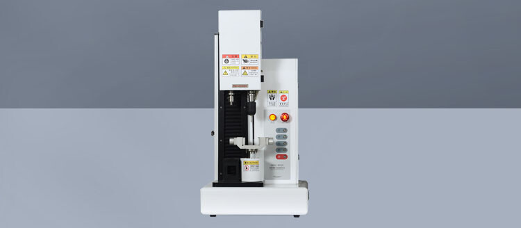

A screw that takes more effort to insert does not necessarily resist extraction more strongly. Insertion testing measures the torque needed to drive a bone screw into a defined material. Pullout testing measures the axial force needed to extract it. These measurements describe different aspects of the screw–material interface, so one cannot reliably replace the other.
A Bone Screw Insertion Tester helps reveal how resistance changes as a screw advances, including the effects of thread engagement, cutting, friction, and seating. A pullout test shows how the resulting engagement withstands direct axial loading. Understanding both results is useful when comparing screw designs, evaluating hole preparation, or investigating why apparently secure insertion produces disappointing retention.
What each test actually measures
Insertion torque is a turning moment: the rotational effort applied through the screwdriver to advance the screw. It is commonly expressed in newton-metres or an appropriate smaller unit. Pullout force is a linear load, commonly expressed in newtons. Because these quantities describe different loading actions, there is no universal conversion between them.
Both tests depend on the substrate, preparation method, and loading conditions. A result therefore describes a screw tested under specified conditions, rather than an independent property of the screw alone.
What a Bone Screw Insertion Tester reveals during advancement
An insertion test becomes more informative when it records the full torque curve instead of reporting only the highest value. Different portions of the curve can reflect different events, and the largest peak may occur after the threads have already reached their intended engagement.
Early resistance may reflect the screw tip entering the hole and the first threads engaging. As insertion continues, torque can change because additional threads contact the material, the screw cuts or forms a path, or friction increases. For a self-tapping design, cutting contributes to the measured resistance. A previously tapped hole changes that interaction and therefore changes what the test evaluates.
Later in the sequence, contact between the screw head and a surface or plate can create a steep torque rise. That rise may mainly represent seating and compression at the head interface. Comparing it directly with the running torque of a screw stopped before head contact would mix two different events.
This distinction matters when assessing a design intended to advance more easily. Lower running torque under matched conditions can indicate reduced insertion resistance. It does not, by itself, establish weaker fixation. The screw may require less cutting effort or create less friction while retaining effective thread engagement.
A sudden torque drop after a rise can suggest loss of engagement, such as stripping of the surrounding material. However, driver slip or an equipment issue can also disturb the curve. Interpreting the signal requires checking the specimen, screw, and drive connection.
Insertion torque, seating torque, and stripping torque should be identified separately. A test stopped at a defined depth answers a different question from one deliberately continued until the interface fails. Reporting all of these as “maximum insertion torque” can conceal the behavior that matters.
What pullout testing reveals after insertion
In a pullout test, the substrate is restrained while a fixture applies load along the screw’s axis. The equipment records force as the screw moves relative to the specimen. Peak force is a common measure of axial retention, but the force–displacement curve and observed failure mode provide useful context.
Pullout resistance develops through the interaction between the threads and the surrounding material. Thread geometry, engaged length, substrate structure, and damage created during insertion all influence that interaction. Failure can involve shearing or crushing material around the threads, fracture of the specimen, or another failure within the load path.
The failure location affects the conclusion. If the specimen splits or the fixture slips before the screw–substrate interface fails, the recorded peak may not represent the intended pullout mechanism. Photographs and a short description of the failed specimen can therefore make the numerical result much easier to interpret.
Initial curve behavior also needs care. Fixture clearance, alignment changes, and compliance in the testing system can influence the early displacement reading. A displacement measured at the machine crosshead is not automatically identical to movement at the screw–material interface.
Axial pullout testing is useful for comparing resistance to direct extraction under controlled conditions. It does not establish performance under repeated loading, bending, sideways movement, or every condition within a complete fixation assembly. Those questions require tests that reproduce the relevant loading mechanism.
Why higher insertion torque does not guarantee higher pullout strength
The two measurements can move together because both depend partly on thread engagement and substrate properties. Within a tightly controlled comparison, stronger engagement may increase both insertion resistance and extraction resistance. That relationship becomes less dependable when other variables change.
For example, a smaller pilot hole may increase insertion torque because the screw displaces or cuts more material. If preparation becomes too restrictive for the screw and substrate, the additional resistance may also cause damage. The high torque then reflects an aggressive insertion process without proving improved retention.
Head seating provides another reason for disagreement. Two screws may develop similar engagement along their threads, while one produces a larger torque peak because its head contacts a different surface. Their peak insertion values could differ substantially without an equivalent difference in axial pullout force.
Stripping makes the problem clearer. A screw can reach a high torque and then damage the material supporting its threads. Reporting only that earlier peak makes the insertion appear strong, even though the final interface has lost resistance.
Consider a hypothetical comparison in which one screw design requires less running torque but reaches similar pullout force in matched specimens. That finding would support easier insertion with comparable axial retention under those conditions. It would not justify a broader claim about clinical performance or every substrate.
The useful approach is to compare both measurements within a defined test setup and explain any disagreement through the curves and failure observations. Treating insertion torque as a universal predictor of pullout strength removes precisely the information that the second test provides.
The conditions that can change the comparison
Substrate structure and specimen geometry
Synthetic test blocks offer controlled materials for repeatable comparisons. Biological bone can provide structural features that a uniform block does not reproduce, but it also introduces variation in density, cortical thickness, internal architecture, and condition.
A result from one substrate should not be transferred automatically to another. The same screw may engage differently in a uniform foam block, a layered model, and a specimen with a substantial cortical shell.
Block dimensions and hole location matter too. Nearby edges, previous holes, and insufficient spacing can alter local support or create interacting damage zones. Using fresh, adequately separated insertion sites helps keep the comparison focused on the intended variables.
Pilot holes, tapping, and engagement depth
Pilot-hole diameter and depth change how much material the screw encounters. Tapping changes whether the screw cuts its own thread path or follows an existing one. Countersinking can alter head contact and seating behavior.
These preparation choices must be documented and controlled unless they are the subject of the study. Otherwise, an apparent design advantage may actually be a difference in the hole preparation.
Insertion depth determines how much thread engages the substrate. If two screws are tested at different engaged lengths, their pullout results answer a different question from a comparison at matched engagement. Whether the screw engages one cortical layer or more than one also changes the load path.
Motion control and alignment
Insertion speed, axial force applied through the driver, and the relationship between rotation and axial advancement can affect engagement. The test system must accommodate screw advancement appropriately; forcing axial movement that conflicts with the thread’s advance can introduce unintended loading.
During pullout, the screw axis and loading axis should be aligned. An angled pull adds bending or prying, so the test no longer represents a straightforward axial comparison. The substrate fixture should restrain the specimen consistently without obstructing the intended failure region.
Choosing equipment around the question you need to answer
If the main concern is how a screw advances, the insertion system needs controlled rotation, suitable torque measurement, and a reliable drive connection. Recording torque against rotation or depth helps distinguish entry, running resistance, and seating. Torque against time can also be useful, provided the motion conditions are known.
Sensor range should suit the expected measurement. A range that is unnecessarily large may make small differences harder to resolve, while insufficient capacity can overload the measurement system. Data acquisition must capture meaningful changes in the curve rather than reducing the process to a single peak.
For pullout testing, a mechanical testing frame needs an appropriate force sensor, controlled axial movement, and fixtures suited to the screw and specimen. Fixture stiffness, alignment, and secure head engagement directly affect the quality of the comparison.
A basic axial force setup cannot characterize insertion torque without rotational loading and torque sensing. Likewise, an insertion tester needs suitable axial loading and force measurement capabilities to perform pullout testing. Equipment selection should follow the measurement required, including how motion is controlled and how data are recorded.
Some research questions require additional methods. If the concern is screw breakage under twisting, interface stripping alone does not establish the screw’s torsional strength. If the concern is progressive loosening during repeated loading, a single pullout test captures only one part of the behavior.
Using both tests in a meaningful comparison
When the aim is to connect insertion behavior with subsequent retention, recording insertion and then pulling out the same screw can provide a useful paired result. It preserves the insertion history of that particular interface.
That sequence needs a clear stopping rule. A screw inserted to a defined depth provides different information from one seated against a plate or deliberately driven until stripping. Pullout after intentional stripping measures a damaged interface and should be interpreted accordingly.
Pullout is destructive, so the same hole cannot provide a fresh repeat measurement afterward. Reusing an insertion site also changes the material before testing begins. Separate specimens or undamaged locations are needed for independent comparisons.
A practical test plan should define:
- The screw designs and the specific difference being investigated.
- The substrate, specimen dimensions, and hole preparation.
- The insertion speed, advancement conditions, depth, and stopping criterion.
- The pullout alignment, loading rate, and specimen restraint.
- The torque and force metrics to report, alongside curves and failure observations.
Repeated measurements are needed to distinguish a consistent design effect from specimen variation. Reporting the spread of results alongside typical values makes the comparison more useful than selecting the best-performing specimen.
Begin with the performance question: easier advancement, reliable seating, resistance to axial extraction, or behavior under another loading condition. Then choose measurements that directly address it. When insertion and pullout results disagree, examine preparation, seating, material damage, and failure mode before ranking the screws. The disagreement may reveal the most useful information in the test.
Leave A Reply
Search by Keywords