




What Is A Bone Screw Pull Out Tester?
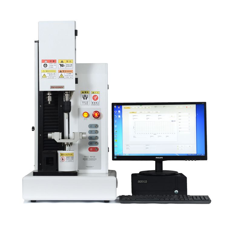
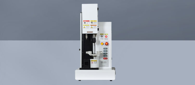
A Bone Screw Pull Out Tester is a mechanical testing system used to measure the axial force required to withdraw a screw from a defined test material. A typical system combines a load frame, a calibrated force sensor, a displacement measurement system, and fixtures that hold the screw and test block in alignment. The resulting force-displacement curve helps engineers compare fixation behavior under controlled laboratory conditions.
Pull-out testing addresses one aspect of screw performance: resistance to axial extraction. It does not independently establish clinical safety, predict every failure mode, or reproduce the complex loading experienced in the body. Thread geometry, insertion depth, substrate properties, and test alignment all influence the measured result, so a reported maximum force is meaningful only when accompanied by the corresponding method and specimen details.
Orthopedic implant manufacturers, independent laboratories, research institutions, and quality teams use these systems during design development, verification, and manufacturing investigations. Purchasing teams should distinguish a complete testing capability from a load frame alone: the appropriate fixtures, control software, calibration, and documented procedure are equally important to obtaining data that can be interpreted and compared.
ASTM F543 And Related Standards
ASTM F543, Standard Specification and Test Methods for Metallic Medical Bone Screws, provides a framework for evaluating specified properties of metallic bone screws. Its test methods address performance characteristics including torsional properties, insertion and removal torque, axial pull-out strength, and self-tapping performance. Applicability depends on the screw and the question being investigated; users should consult the current purchased edition and any applicable product-specific requirements.
For axial pull-out, the standard describes a controlled approach to preparing the test assembly, inserting the screw, applying an axial tensile load, and determining pull-out strength. Details such as the test medium, preparation, loading conditions, and reporting requirements must be taken from the applicable edition rather than assumed from a product brochure. Any deviation should be documented and justified before results are compared.
ASTM F1839 covers rigid polyurethane foam intended as a standard material for testing orthopedic devices and instruments. Synthetic foam can improve consistency when comparing designs, but its selection does not make it equivalent to human bone in every respect. Equipment verification may also involve applicable force and displacement calibration standards. Regulatory submissions require a separate assessment of the relevant jurisdiction, device, and evidence.
How The Pull Out Test Works
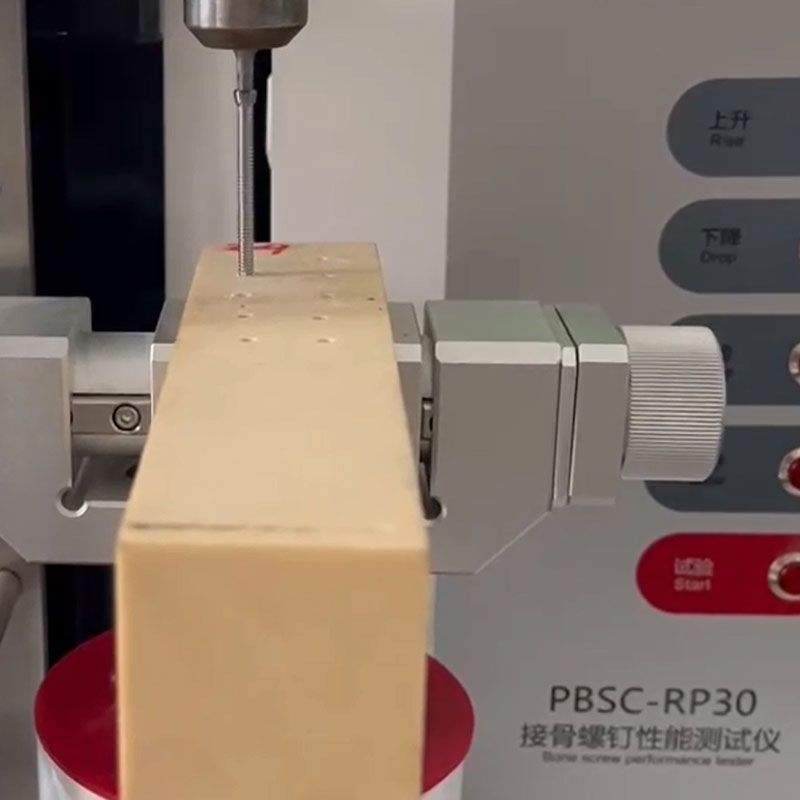
The basic principle is to insert a screw into a prepared test block, grip its head or a suitable attachment, and pull along the screw axis while recording force and displacement. As loading progresses, the screw and surrounding material deform until the assembly reaches a maximum force and begins to lose resistance. The peak force is commonly reported as the axial pull-out strength for that specimen and setup.
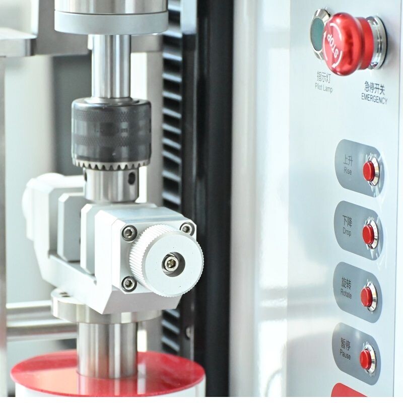
Preparation begins with a defined screw specification, test medium, pilot-hole condition where applicable, and insertion depth. The operator should control insertion technique and record relevant observations, including damage or unusual resistance. A fixture must support the block without allowing movement that changes the loading direction. The grip must transfer force to the screw without introducing significant bending or slipping.
During the test, the controller applies the prescribed motion while software captures the force-displacement trace. Review the curve as well as the peak value: unexpected discontinuities may indicate slippage, fixture movement, or another setup problem. Record the failure mode and retain raw data when required by the test plan. Repeat specimens and assess variation before drawing conclusions about design differences.
Test System Types And Capabilities
Dedicated bone screw systems are configured around common screw fixtures and medical-device test workflows. Multipurpose electromechanical systems can also perform pull-out tests when equipped with suitable load cells, grips, software, and control capabilities. The practical distinction is not simply the machine label: it is whether the complete configuration can execute the intended method across the required force and displacement ranges.
Some laboratories need more than axial extraction. A broader program may assess insertion torque, removal torque, torsional failure, and self-tapping behavior alongside pull-out resistance. These measurements answer different questions and may require separate sensors, fixtures, or machine configurations. Confirm whether a proposed system supports each method directly, through optional accessories, or with a separate instrument.
For laboratories evaluating a dedicated option, paratronix lists the PBSC-RP30 Bone Screw Performance Tester as a related product. Its suitability for a particular ASTM F543 procedure should be established against the proposed configuration, current specifications, and required fixtures. Paratronix also offers testing equipment across torque, multipurpose testing, and medical packaging applications, giving buyers additional areas to discuss when planning laboratory capabilities.
Applications And Data Interpretation
During product development, teams can use a Bone Screw Pull Out Tester to compare thread profiles, diameters, insertion depths, or surface conditions under a consistent protocol. Change one factor at a time where practical, and document the others. A higher peak force in one substrate may be useful design evidence, but it should not be treated as proof of superior performance in all anatomical locations or clinical conditions.
For verification and quality investigations, the test plan should define specimen selection, acceptance criteria, sample size rationale, and actions for invalid tests before testing begins. Compare results only when the screw, substrate, preparation, and loading conditions are sufficiently aligned. Differences in foam grade, pilot-hole geometry, or fixture design can make numerical comparisons misleading even when both reports refer to ASTM F543.
For market submissions or customer qualification, retain traceable records of specimen identity, equipment configuration, calibration status, procedure revision, raw data, and deviations. A laboratory report should distinguish results obtained under a standard method from supplementary or modified testing. The applicable regulatory pathway and evidence expectations vary by market and device; confirm them with the relevant authority or qualified regulatory specialist.
Selection Criteria And Total Cost
Start selection with expected force levels, screw dimensions, test materials, and the methods in the laboratory test plan. Choose a load cell with sufficient capacity for the expected peak while maintaining suitable measurement performance across the forces of interest. Check the usable crosshead travel, speed control, data acquisition, and displacement measurement arrangement. Request documented specifications and verify that they apply to the complete proposed configuration.
Fixture compatibility deserves particular attention. Ask how the block is secured, how the screw is aligned, which head geometries can be gripped, and whether adapters are included. Evaluate software for curve capture, data export, access control, and reporting against internal requirements. Installation, operator training, calibration support, spare parts, and service response are purchasing considerations, especially for laboratories that must maintain traceable records.
Total ownership cost includes the machine, fixtures, sensors, software, installation, calibration, maintenance, consumable test blocks, and operator time. Compare these costs with expected test volume and the expense and turnaround of outsourced testing. An investment case should also consider capacity utilization and the cost of retesting after invalid setups. Ask suppliers for an itemized quotation and identify optional accessories before comparing prices.
Quality Control And Future Trends
Reliable results depend on routine control of both equipment and procedure. Establish calibration intervals based on the applicable requirements, manufacturer guidance, usage, and laboratory risk assessment. Inspect grips and fixtures for wear, confirm alignment, and verify software settings before a test series. When components are changed or equipment is moved, assess whether additional checks are needed before results are accepted.
Digital traceability, more consistent fixture setups, and broader evaluation of implant-device interactions are likely to remain important directions for testing laboratories. Automated data capture can reduce manual transcription, but it does not replace method validation or operator review. As standards and device designs evolve, laboratories should periodically review their procedures, substrate choices, and equipment capabilities against current project and regulatory needs.
To discuss a suitable configuration, provide paratronix with the screw drawings, expected force range, test medium, applicable standard edition, and required outputs. Ask for confirmation of fixtures, calibration scope, software functions, and service arrangements for the PBSC-RP30 or another proposed solution. For related measurements, consult the article Self-Tapping Screw Tester Metrics for Torque, Insertion, and Pull-Out Testing.
Search by Keywords