




Recent Posts
 Which Features Have the Greatest Impact on Puncture Force Tester Cost?Sep 17, 2026
 Bone Screw Torsion Tester Requirements for ASTM F543 Mechanical TestingSep 17, 2026
 Self-Tapping Screw Tester Metrics for Torque, Insertion, and Pull-Out TestingSep 17, 2026
 Non-Destructive Sealing Tester Methods for Blister Pack Integrity ControlSep 17, 2026
 ASTM and ISO Requirements for Plastic Film Puncture Force Test Method ValidationSep 16, 2026
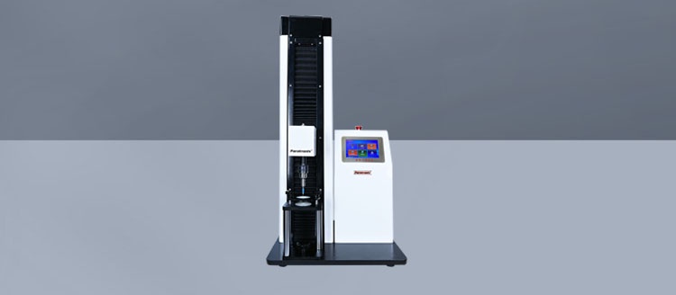
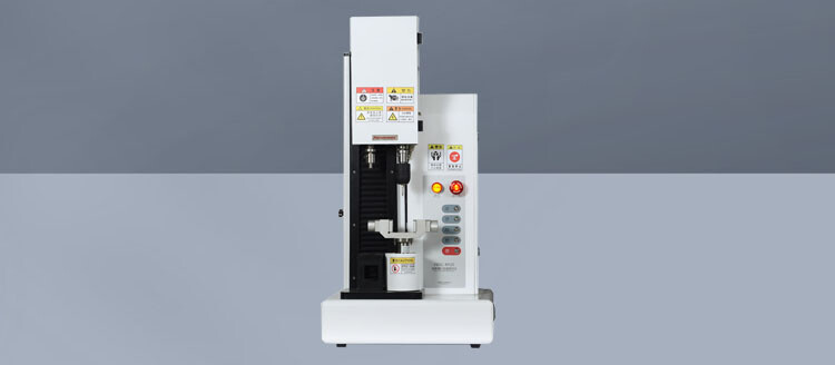
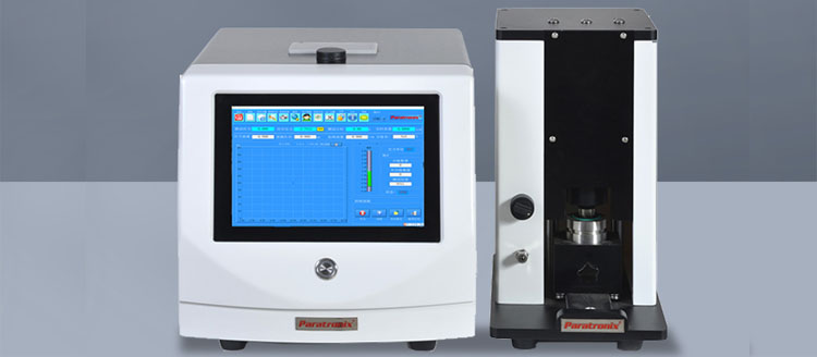
A fastening problem may first appear as an assembly complaint: a screw suddenly spins without tightening, a closure cracks during installation, or a threaded insert pulls out after handling. In packaging components, plastic housings, barrier structures, and molded parts, these failures can be difficult to trace because a screw may install normally on one production batch and behave differently on the next.
A Self Tapping Screw Tester should therefore be evaluated by the metrics it can measure and the test conditions it can control, not simply by its maximum force or torque range. The core measurements are usually insertion torque, seating torque, stripping torque, pull-out force, and displacement. Together, they reveal whether the fastening system has adequate thread-forming capability, installation consistency, and retention strength. A valid result also depends on using the actual screw, substrate geometry, pilot-hole condition, insertion speed, and fixture alignment expected in service.
The measurements that describe fastening performance
Self-tapping screws create or form threads in the receiving material during installation. Their performance is not described by one number alone. Torque data explains the resistance encountered while the screw engages the material, while axial force data shows how securely the formed thread resists withdrawal. A tester that records both signals over time or displacement gives a more useful picture than a single peak-value measurement.
The relationship between these values is often more informative than any individual reading. A high insertion torque does not automatically mean strong retention. It may result from excessive friction at the screw tip or from an undersized pilot hole, yet the material may still strip before the intended clamp condition is reached. Conversely, a low insertion torque can be acceptable where the screw geometry and substrate are designed for it, provided stripping torque and pull-out resistance remain within the required limits.
Insertion torque: separating useful thread forming from excessive resistance
Insertion torque is the rotational torque recorded as the screw enters the specimen and forms, cuts, or displaces material to create a mating thread. During a controlled test, the torque trace commonly rises as the screw tip begins engagement, fluctuates as successive threads enter the material, and changes again near final seating. The shape of this curve can point to process differences that a peak value alone may hide.
For example, a smooth and repeatable torque profile across specimens generally suggests stable material and installation conditions. Sharp spikes may be associated with local hard regions, contamination, misalignment, abrupt contact with a molded feature, or an irregular pilot hole. A gradual upward drift over a sequence of samples can indicate that screw driving conditions, tool wear, or part dimensions should be checked.
Technical evaluation should distinguish between the torque needed to form threads and the torque applied after the screw has reached the intended depth. These are separate stages. If the test continues after seating without a defined stop rule, the recorded maximum may mainly reflect over-tightening rather than normal installation performance. That can make comparisons between materials misleading.
Conditions that must be fixed during insertion testing
- Rotational speed: Polymer materials can respond differently at different drive speeds because frictional heating and viscoelastic deformation may change the torque profile.
- Axial feed or downforce: Too little axial support can cause cam-out or irregular engagement; excessive force can alter the way the screw enters the specimen.
- Insertion depth: Define whether the endpoint is a set depth, a head-contact condition, a torque limit, or a fixture stop.
- Screw condition: Coating, tip design, thread form, nominal diameter, and reuse status can all change the result. Used screws should not be mixed with unused screws unless reuse is itself under study.
- Pilot-hole geometry: Diameter, roundness, depth, and position relative to edges or ribs should represent the intended part condition.
Where the product specification includes an allowable installation window, insertion torque is commonly assessed together with stripping torque. The important question is whether the normal assembly torque remains safely below the stripping threshold while still providing reliable seating. A narrow margin can create production risk even when both values appear acceptable in isolation.
Stripping torque and the usable installation window
Stripping occurs when the receiving material can no longer sustain the formed thread under rotation. The screw may continue to turn, but it no longer advances or produces meaningful clamp load. In thin plastic sections or materials with limited thread engagement depth, stripping can occur quickly after seating. It is especially important to identify this point when a fastening system will be installed by powered equipment.
A stripping torque test normally drives the screw beyond the intended seating condition under controlled rotation until thread failure is detected. Depending on the system and method, failure may be identified by a sudden torque drop, sustained rotation without axial advancement, a specified change in torque slope, or direct observation of stripped material. The selected criterion must be defined before comparisons are made.
The useful installation window is the difference between the torque required to achieve proper seating and the torque that causes stripping. A broad window gives assembly equipment more tolerance for normal variation. A narrow window may require tighter control of driver settings, part dimensions, or screw selection. It may also suggest that the joint design should be reviewed rather than attempting to solve the issue only through tool adjustment.
It is a mistake to treat the highest stripping torque as the only desirable outcome. An aggressive thread-forming design can increase resistance, but it may also raise insertion demands, stress the substrate, or create cracks around the boss. The better design is one that reaches the required retention and seating behavior without imposing avoidable installation damage.
Pull-out force: testing retention after the screw is installed
Pull-out testing measures the axial force required to remove an installed screw from the substrate. It is particularly relevant where the service load tends to act parallel to the screw axis, such as a cover being lifted, a component being pulled away from its mounting point, or a package feature being subjected to handling forces. Pull-out force does not replace torque testing; it assesses a different failure mode.
The specimen should be held so that the extraction force is aligned as closely as possible with the screw axis. Even a small angular offset can introduce bending, side loading, or local fixture contact that changes the measured force. The pulling grip must engage the screw head or designated attachment point securely without slipping or distorting the sample.
A force-displacement curve helps distinguish several types of behavior:
- A rising force followed by a clean peak and withdrawal may indicate thread pull-out.
- A sudden low-displacement failure may point to cracking, boss fracture, or failure near an edge.
- Extended displacement with fluctuating force can occur when threads progressively disengage or material deforms before release.
- Failure of the screw itself, or failure at the grip rather than the substrate, means the method may not be measuring the intended joint performance.
Extraction speed should remain controlled because rate-sensitive materials may show different pull-out behavior at different crosshead speeds. The required speed should come from the applicable internal method, product requirement, or recognized test procedure where one governs the application. If no external method applies, the laboratory should establish and document a repeatable speed, alignment approach, and failure classification rule.
Why torque and pull-out results can disagree
A joint with high stripping torque may still have modest pull-out resistance. This can happen when a screw creates a tight local fit but has limited engagement length, when the substrate has a thin wall, or when the material resists rotation better than axial thread withdrawal. Similarly, strong pull-out force does not prove that the screw can be installed safely on the line; insertion torque may be too high for the available driver or may cause cracking during seating.
When results do not move together, review the mechanics before assuming the tester is at fault. Check the screw engagement depth, screw pitch, minor and major diameter, pilot-hole size, local material thickness, molded boss design, and distance from unsupported edges. For multilayer or high-barrier structures, consider whether the screw is engaging a homogeneous support layer or passing through layers with different stiffness and fracture behavior.
Material conditioning also matters. Plastics can change in stiffness and toughness with temperature and humidity. A sample set tested immediately after molding may not behave like parts stored under the normal assembly or use environment. A meaningful comparison requires the conditioning period and test environment to be stated with the results.
Building a repeatable test sequence
Reliable screw testing starts before the machine begins recording. Samples should be identified by material lot, geometry, conditioning state, and relevant manufacturing variables. The aim is not to create unnecessary paperwork; it is to make a result traceable when an unexpected torque shift or pull-out failure appears later.
- Inspect the specimen for visible damage, incomplete molding, warpage, contamination, or pre-existing cracks around the fastening location.
- Verify the screw type and dimensions. Use consistent screw condition and confirm that the driver bit matches the head profile.
- Install the specimen in a rigid fixture that supports the actual load-bearing area without crushing or artificially reinforcing the joint.
- Set rotational speed, axial feed, depth or seating endpoint, and data acquisition parameters before the first specimen is tested.
- Run the insertion stage while recording torque and, where available, axial travel or insertion depth.
- For stripping evaluation, apply the defined continuation procedure after seating and record the failure point and failure appearance.
- For pull-out evaluation, reconfigure the fixture as needed, align the pull axis with the screw axis, and record force and displacement to failure.
- Review curves as well as peak values. Classify whether each specimen failed by thread stripping, pull-out, cracking, screw damage, or a non-valid fixture-related event.
A fixture deserves particular attention. A poorly supported molded boss may flex during insertion and artificially reduce measured torque. A clamp placed too close to the screw can increase apparent pull-out resistance by restraining deformation that would occur in the real component. The fixture should stabilize the sample while preserving the relevant failure mechanism.
Interpreting result variation before changing the design
When a result falls outside the expected range, changing the screw or substrate immediately can hide the real cause. Start by comparing torque and force curves from conforming and nonconforming samples. Look for a shifted baseline, an early spike, irregular oscillation, a changed seating point, or a different displacement at failure. These patterns often direct the investigation more effectively than comparing peak numbers alone.
Then separate variation into likely sources: material condition, molded geometry, pilot-hole quality, screw variation, tool setup, fixture alignment, and operator or automated drive settings. A test series with controlled changes is more useful than testing many mixed-condition specimens. For instance, pilot-hole diameter can be evaluated while holding screw batch, speed, conditioning, and sample geometry constant. That makes it possible to see whether the hole is influencing insertion torque, stripping behavior, pull-out force, or all three.
Do not average away clear differences in failure mode. Two specimens may produce similar maximum pull-out force while one fails through gradual thread release and another through brittle boss fracture. Their numerical average may look stable, but their engineering implications are not the same.
Instrument capabilities that matter during evaluation
When specifying a Self Tapping Screw Tester, confirm that its torque sensor and force sensor cover the expected range with sufficient resolution for the smallest meaningful change. Excessive capacity can reduce practical sensitivity, while insufficient capacity risks overload or incomplete failure data. The system should also control rotational speed and axial movement consistently, support secure specimen fixturing, and capture torque, force, displacement, and time in a synchronized record.
For development work, the ability to view full test curves is valuable because it supports comparison of insertion stages, seating behavior, stripping onset, and extraction failure. For routine quality control, repeatable test recipes and clear acceptance logic help reduce setup variation between operators. Calibration status, sensor zeroing, driver-bit condition, and fixture inspection should be maintained as part of the method, since these factors directly affect measurement confidence.
The final test method should reflect the real joint rather than an idealized sample. A screw tested in a thick, flat coupon may provide useful material screening data, but it cannot automatically predict performance in a thin-walled molded feature, a layered package component, or a geometry close to an edge. The most defensible torque, insertion, and pull-out data comes from a controlled method that reproduces the actual fastening conditions closely enough to expose the failure modes that matter.
Leave A Reply
Search by Keywords