




Recent Posts
 What does a Luer taper ease of assembly tester measure?Oct 31, 2026
 What does ISO 80369-7 require for Luer ease of assembly tests?Oct 31, 2026
 What Does a Luer Taper Easy Assembly Tester Measure?Oct 30, 2026
 Luer Easy Assembly Testing Under ISO 80369-7: Key RequirementsOct 29, 2026
 What Does a Luer Taper Resistance-to-Overriding Tester Actually Measure?Oct 29, 2026
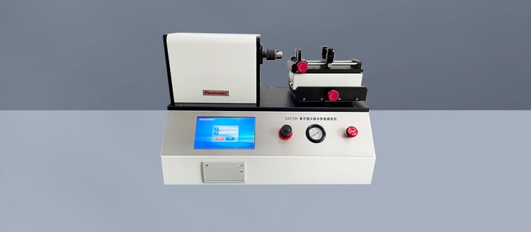
ISO 80369-7 addresses Luer connectors for intravascular or hypodermic applications, but an ease of assembly result is meaningful only when it is tied to the applicable standard edition, connector configuration and specified test method. The assessment concerns whether the connectors can be brought together under defined conditions without unacceptable difficulty or damage. A measured force or torque on its own does not establish conformity: the preparation, reference connector, assembly procedure and acceptance criteria must also match the applicable requirements.
The controlled copy of ISO 80369-7, together with the relevant parts of the ISO 80369 series it references, is the authority for the exact procedure and limits. Test plans should identify the editions used and distinguish a formal conformity test from an internal comparison of assembly force. This distinction matters because a device can assemble smoothly against one mating part and behave differently against a reference connector with a different allowable geometry.
What the assembly test is intended to establish
A Luer connection relies on mating surfaces that must engage predictably. For a locking connection, the thread or locking feature also has to engage without preventing the tapered surfaces from seating as intended. The ease of assembly assessment examines that process under specified conditions. Depending on the applicable method and connector design, the controlled inputs can include axial loading, rotational motion, alignment and the characteristics of the mating connector.
Resistance during assembly has several possible sources. Taper interference can generate axial resistance; thread engagement can add rotational resistance; and friction depends on surface finish and material pairing. A locking feature that catches early can create a torque peak even when the taper itself is acceptable. Conversely, low resistance does not necessarily indicate a sound connection: insufficient engagement or an incorrectly sized component can also produce an easy initial fit.
For this reason, the outcome must be evaluated using the standard's specified endpoint and acceptance criteria. An instrument's peak force display is useful only if peak force is an attribute required or deliberately monitored by the chosen method. A curve or numerical value should not be substituted for a prescribed visual or functional assessment.
Start with the correct standard and connector configuration
ISO 80369-7 covers a defined family of small-bore connectors; it should not be treated as a generic assembly specification for every fluid connection. Establish whether the specimen is a male or female Luer component, whether it incorporates locking features, and whether its intended application falls within the standard's scope. The connector may be an integral part of a syringe, fitting or other device, so the specimen configuration used in the test must also be defined.
The applicable edition determines which requirements, test methods and references apply. A test document should identify the exact clause or annex used, including any referenced procedure from another part of the ISO 80369 series. Where the governing documents refer to a reference connector, its specified characteristics and condition form part of the test setup. A commercially available mating component is not automatically an acceptable substitute simply because it fits.
Changes between editions can affect the interpretation of a result. A historical report remains evidence of the procedure performed at the time, but it should not be relabeled as evidence against a later edition without reviewing the differences. The same caution applies when comparing reports that use different specimen preparation or mating hardware.
Conditions that affect the result
Reference connector and alignment
The reference connector provides a controlled mating surface against which the specimen is assessed. Its taper, locking features, surface condition and material should correspond to the applicable method. Scratches, adhered material or wear on a reusable reference part can alter friction and engagement. Identification and inspection records make it possible to trace an unexpected change in results to the mating part rather than immediately attributing it to the specimen.
Alignment is equally important. If the connector axes are offset or tilted, one side of the taper can contact first. The resulting resistance may look like a tight fit even though the fixture is imposing a side load. Fixtures should support the specimen securely without crushing the connector, distorting a flexible device or obstructing the movement required by the procedure.
Axial force and rotation
Assembly force and torque describe different actions. Axial force pushes the mating parts together; torque turns a component around its axis. In a locking Luer, the two actions interact, but a torque reading cannot be converted into an axial force without assumptions about friction, geometry and thread behavior. The test record should therefore preserve the units and identify which quantity was controlled and which was measured.
Motion sequence also matters. Starting rotation before the mating parts are correctly aligned can cause a locking thread to ride over its counterpart or engage unevenly. Excessive axial preload can increase friction before the locking feature advances. Where the standard specifies the order, direction, rate or endpoint of movement, those conditions must be reproduced; changing them for convenience creates a different test.
A force or torque peak at the start of motion may indicate initial contact, a fixture issue or interference at a locking feature. A peak near the end of travel may instead reflect seating or the prescribed endpoint. The point at which a peak occurs is therefore valuable diagnostic information, even when the formal decision is based on another criterion.
Specimen preparation
Temperature, conditioning, cleaning and handling can influence a polymer connector's stiffness and surface friction. Test specimens in the condition required by the applicable method, and record any preparation that could alter the mating surfaces. Lubrication, deliberate cleaning or repeated mating should not be introduced unless permitted or required by the test procedure.
Reuse deserves particular attention. A first assembly can mark a surface or deform a locking feature, changing the resistance on the next attempt. When the method requires fresh specimens or limits reuse, an exploratory trial on the same connector can invalidate the subsequent formal result. Development trials should be identified separately from specimens reserved for conformity testing.
Using assembly testing equipment
A Luer Taper easy assembly Tester can apply and monitor the motions relevant to an assembly procedure, provided its configuration matches the specified method. The equipment itself does not make a test compliant. The fixtures, reference connector, measurement channels, control settings and data handling must support the required procedure as a complete system.
Axial and rotational measurements should have suitable ranges and traceable calibration. A sensor selected for a much higher load than the test requires can have inadequate resolution at the working point. Fixture friction and the weight or resistance of moving parts can also affect a low-load measurement. A documented zeroing procedure and an assessment of the measurement setup help distinguish specimen behavior from instrument effects.
The fixture should hold the device by a representative and mechanically stable area. Clamping directly on a thin connector wall may change its shape; gripping a flexible tube can allow the specimen to twist before the connector moves. Where the procedure calls for a particular freedom of movement, an overly rigid fixture can alter the result just as an unstable fixture can.
Software settings are part of the method record. The acquisition rate should be adequate to capture the events being evaluated, particularly short peaks. Filtering or averaging can make a noisy signal easier to read, but it can also reduce a real peak. Store the relevant raw data or preserve a clear record of the processing applied, especially when a result is close to an acceptance limit.
Reading a difficult assembly result
A high reading does not identify its own cause. Examine the specimen and reference connector at the location and stage associated with the resistance. A raised molding feature, damaged thread, contamination or an off-axis fixture can produce similar numerical results while requiring very different corrective actions. If a locking feature is involved, note whether it engaged normally, skipped, jammed or showed visible deformation.
A low reading also needs context. The parts may have entered easily because they were not fully engaged, because a locking feature did not catch, or because the fixture stopped travel too early. Compare the actual endpoint with the endpoint required by the method before interpreting low resistance as favorable.
When a result is close to a limit, measurement uncertainty and setup variation deserve attention. An individual result must still be assessed according to the applicable decision rule; uncertainty should not be used informally to change a specified limit. If the standard or governing test plan defines rounding or an acceptance rule, apply it consistently and document it.
Retesting after an unexpected result requires a defined rationale. Correcting a demonstrated equipment fault and repeating an invalid test is different from discarding a valid unfavorable result. Preserve the original observation, the reason for any invalidation, the corrective action and the identity of replacement specimens. Repeatedly assembling the same part until it passes can obscure damage or wear introduced by earlier attempts.
Assembly is separate from other connection performance
Ease of assembly does not by itself establish leak resistance, resistance to separation or continued performance after other stresses. Those properties are addressed by the applicable requirements and tests for the connector. A connection can assemble readily yet fail a later functional assessment; it can also be difficult to assemble while showing acceptable performance after engagement. Each result answers a different question.
For an interpretable report, retain the standard and edition, the relevant procedure, specimen identification and condition, reference connector identification, equipment and calibration status, settings, observations, measured results and the stated acceptance decision. Record deviations explicitly. This allows a later reviewer to determine whether a difference between two results reflects the connector itself or a change in the test conditions.
Leave A Reply
Search by Keywords