




Recent Posts
 Luer Easy Assembly Testing Under ISO 80369-7: Key RequirementsOct 29, 2026
 What Does a Luer Taper Resistance-to-Overriding Tester Actually Measure?Oct 29, 2026
 ISO 80369-7 Luer Lock Overriding Tests: What Your Equipment Must SupportOct 29, 2026
 Axial Load, Torque, and Hold Time in Luer Connector Stress Cracking TestsOct 28, 2026
 ISO 80369-7: Planning Stress Cracking Tests for Luer ConnectorsOct 28, 2026
What Does a Luer Taper Resistance-to-Overriding Tester Actually Measure?
A secure Luer Taper connection depends on more than a tight fit. Its locking features must remain engaged when tightening torque is applied. A resistance-to-overriding tester evaluates whether those features resist slipping past one another under specified test conditions. Unlike a leakage or separation test, this assessment focuses on the mechanical integrity of the locking engagement during tightening.
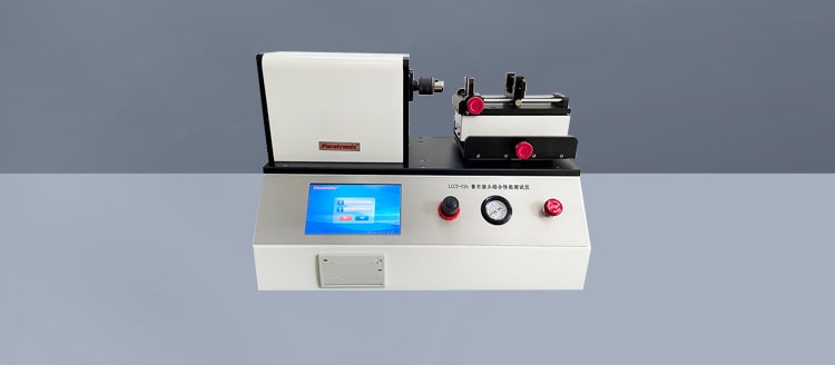
Equipment described as a Luer Taper resistance to slip wire Tester is generally intended to address this question, although “slip wire” is not the clearest English description. The relevant behavior is thread or lug override—not an electrical wire slipping. Understanding that distinction helps pharmaceutical packaging and medical device teams interpret results and assess whether an instrument performs the test they actually need.
The measurement concerns the lock, not simply the taper
A Luer connection combines functions that are easy to confuse. The mating tapered surfaces establish the fluid connection, while the locking features help retain the assembled components. Depending on the design, engagement can involve a threaded collar and mating lugs or other compatible locking geometry.
During normal tightening, rotation advances the locking engagement and seats the connection. Overriding occurs when the locking features pass over or past their intended engagement instead of continuing to restrain movement. Local deformation, inadequate engagement, or damage may allow that movement. The connection can appear assembled even though the locking interface has not behaved as intended.
The tester therefore applies a defined tightening challenge and supports a specific judgment: does the locking mechanism resist overriding under the prescribed conditions? It does not automatically establish the connector’s maximum strength, leak tightness, or suitability for every clinical handling situation.
That distinction matters when someone describes a result as “connection strength.” Strength against what—tightening torque, axial pulling, unscrewing, or internal pressure? These are different loading conditions, and a satisfactory result under one does not establish performance under the others.
Applied torque is the input; resistance to override is the finding
At the instrument level, the central controlled quantity is tightening torque. A suitable system applies that torque through fixtures that hold and drive the relevant connector components. Depending on the equipment, it may also record time, angular movement, and a torque-versus-angle trace.
However, the numerical torque reading and the test conclusion are not the same thing. A display showing that the target torque was reached does not, by itself, prove that the locking interface remained intact. The method must also establish how overriding is identified and how the specimen is assessed.
A sudden torque drop accompanied by continued rotation may indicate loss of engagement. But a similar signal could come from a slipping fixture, movement elsewhere in the assembly, or an issue with the drive arrangement. Recorded curves are useful evidence, not self-explanatory verdicts. Where available, angular data and specimen inspection help distinguish connector behavior from test-system behavior.
There is also a practical difference between a conformity test and a development experiment. A conformity test asks whether a specimen meets a specified requirement. An exploratory test may continue loading to investigate when and how failure occurs. The latter can support design work, but its failure torque should not be substituted for the prescribed conformity assessment.
Why other Luer tests cannot answer the same question
An assembled connector can satisfy one performance requirement and still have a weakness elsewhere. For example, contact between the tapered surfaces may temporarily maintain a seal even when the locking features are compromised. Conversely, a mechanically secure locking interface does not rule out a sealing defect.
These assessments complement one another. Treating a pressure test or a pull test as a substitute for an overriding test leaves a different failure mechanism unexamined.
The test setup can change the meaning of the result
Connector tests are sensitive to how the load reaches the specimen. If a fixture clamps a flexible collar too tightly, it may reinforce or distort the part being evaluated. If the fixture slips, the instrument may report rotational movement that never occurred at the locking interface. Neither result describes the connector accurately.
The mating component matters just as much. Testing against a specified reference connector serves a different purpose from testing two finished commercial components together. A reference connector provides a controlled interface for the applicable method; a finished mating device can help investigate a particular assembly. Results should identify which arrangement was used rather than treating the two as interchangeable.
Before comparing results between laboratories or instruments, check these details:
- Assembly procedure: How were the components initially engaged, and what assembly conditions were specified?
- Torque application: What target, application rate, duration, and stopping conditions were used?
- Restraint and alignment: Which component was driven, and how were unintended movement and distortion prevented?
- Specimen condition: What conditioning, processing history, and prior use were documented?
- Decision rule: What observation or recorded evidence established that overriding had occurred?
The method should also specify whether fresh specimens are required. Reusing a connection can change its contact surfaces and engagement behavior, so a previously tested specimen should not be assumed equivalent to an unused one.
Which standards and parameters should guide the assessment?
For Luer connectors within its scope, ISO 80369-7 is a relevant starting point. ISO 80369-20 addresses common test methods for small-bore connectors. The applicable editions, referenced methods, connector classification, and product requirements should be checked before selecting settings or accepting a supplier’s proposed procedure.
There is no sound reason to choose a torque value simply because another laboratory uses it or because it appears in an equipment brochure. The required torque, timing, assembly conditions, reference connectors, and acceptance criteria need to come from the applicable method and approved test plan. A standards reference on a product page is not evidence that every relevant requirement is implemented.
Instrument specifications deserve the same scrutiny. Torque capacity is only one consideration. Resolution, measurement accuracy, calibration coverage, control behavior, and fixture suitability must be appropriate around the actual test point. A wide measurement range does not necessarily provide better evidence for a low-torque connector test.
What a failed test can—and cannot—tell a design team
A confirmed override directs attention toward the locking interface, but it does not identify a single root cause. Possible contributors include engagement geometry, dimensional variation, local stiffness, material behavior, or damage. The mating interface and assembly procedure must also be considered before attributing the failure to the tested component alone.
Useful follow-up work may include examining the contact features, checking relevant dimensions, reviewing molding conditions, and comparing specimens with different documented processing histories. If sterilization or aging is relevant to the product, its potential influence should be investigated through the validation plan—not assumed from an isolated result.
A passing result has boundaries too. It supports the conclusion that the tested specimens resisted overriding under the recorded conditions. It does not show unlimited resistance to overtightening, demonstrate repeated-use durability, or replace the rest of the connector performance evaluation. Keeping that boundary clear prevents a narrow mechanical result from becoming an unsupported product claim.
Assess the evidence an instrument can produce
When reviewing a Luer Taper resistance to slip wire Tester, look beyond whether it has a torque display and an automatic cycle. Ask how it detects or supports identification of overriding, how fixtures accommodate the intended connectors, and what the report preserves. A useful record connects specimen identity, method revision, settings, calibration status, mating component, observations, and the final judgment.
Paratronix Instruments Co., Ltd. develops and manufactures packaging testing instruments for pharmaceutical packaging, plastic packaging materials, high-barrier materials, and other applications. In discussions with a testing-equipment manufacturer, that broader laboratory context is useful: connector testing may need to fit existing reporting, calibration, and quality workflows. Nevertheless, suitability for an overriding test must be confirmed through the specific instrument configuration and method requirements, not inferred from a general equipment portfolio.
The practical next step is to define the connector, applicable method, mating interface, and required evidence before comparing machines. The right setup should make it possible to distinguish genuine locking-feature override from fixture slip or unrelated movement—and leave a record clear enough for someone else to review that conclusion.
Leave A Reply
Search by Keywords