




Recent Posts
 Luer Easy Assembly Testing Under ISO 80369-7: Key RequirementsOct 29, 2026
 What Does a Luer Taper Resistance-to-Overriding Tester Actually Measure?Oct 29, 2026
 ISO 80369-7 Luer Lock Overriding Tests: What Your Equipment Must SupportOct 29, 2026
 Axial Load, Torque, and Hold Time in Luer Connector Stress Cracking TestsOct 28, 2026
 ISO 80369-7: Planning Stress Cracking Tests for Luer ConnectorsOct 28, 2026
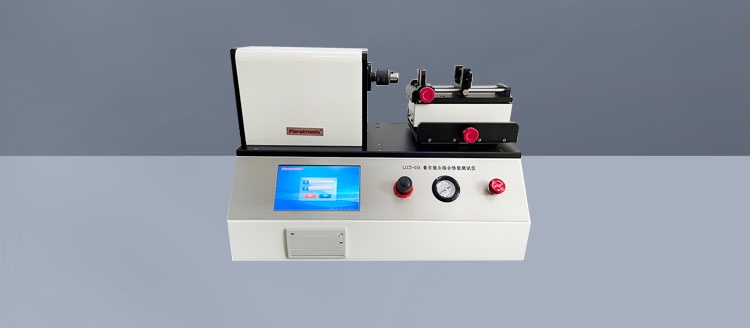
Selecting a Luer Taper resistance to slip wire Tester for ISO 80369-7 overriding tests requires more than checking its maximum torque rating. Technical evaluators need to establish whether the equipment supports the specified loading conditions, secure connector positioning, controlled torque application, and reliable observation of thread or lug overriding. Otherwise, results may reflect fixture movement or inconsistent setup rather than connector performance.
The purchasing decision therefore starts with a practical question: can the system apply the required mechanical challenge to the intended connector interface—and provide enough evidence to show what happened? That question connects the standard, the fixture, the measurement system, and the final test record.
Understand the failure mode before evaluating the instrument
A Luer lock connection combines a tapered fluid interface with a locking feature. Depending on the design, engagement may involve an internally threaded collar and mating external lugs or threads. Resistance to overriding concerns the ability of those locking features to resist riding over one another under the prescribed tightening challenge.
This is not simply a measurement of tightening torque. Nor is it interchangeable with resistance to unscrewing, axial separation, or leakage. These evaluations address different performance characteristics, even when the same testing platform can perform several of them.
A connection might remain assembled after a test yet still have experienced overriding. Conversely, a sudden torque decrease does not automatically prove that the threads or lugs overrode: a specimen may have slipped inside its holder. The equipment must make those possibilities distinguishable.
The commercial expression “resistance to slip wire” is sometimes used for this type of tester. For technical specifications and reports, however, resistance to overriding is the clearer term. Translating the purchasing keyword into the correct test terminology helps prevent suppliers from proposing a general torque instrument that lacks the necessary fixtures or controls.
Translate ISO 80369-7 into an equipment specification
ISO 80369-7 addresses small-bore connectors for intravascular or hypodermic applications. Its requirements must be read alongside the applicable referenced test methods, including relevant provisions of ISO 80369-20. Before comparing instruments, identify the editions and amendments required by your regulatory, customer, or internal verification plan.
Do not build an equipment specification from a supplier’s abbreviated standards list. Extract the actual test conditions from controlled copies of the applicable documents.
Exact numerical settings should come from the applicable standard, not from a generic article or an instrument’s default program. Where software includes a named ISO method, compare every relevant setting against your controlled procedure. A recognizable program name is not evidence that the implementation matches your required edition.
The fixture can determine whether the result is meaningful
Imagine a torque trace that rises smoothly, then drops sharply. It looks like a clear failure until the operator notices that the connector body has rotated inside the clamp. The instrument measured a real event—but not the event the test was intended to assess.
Good fixturing prevents this ambiguity without changing the connector’s behavior. A holder must resist the applied load while avoiding deformation of the locking collar, reinforcement of vulnerable features, or contact that obstructs normal engagement.
Hold the intended component, not the mechanism being tested
Fixture drawings should identify the gripping surfaces and explain how torque is transferred. This matters particularly for connectors with rotating collars, short bodies, thin walls, or limited accessible gripping areas. Clamping the wrong component can immobilize a feature that should remain free, creating a test arrangement that no longer represents the prescribed loading.
Ask the supplier to demonstrate your actual connector geometry. A demonstration using a large, rigid sample may reveal little about a small pharmaceutical connector with a flexible body.
Keep alignment and mating components under control
Misalignment can introduce bending and uneven engagement. The fixture should provide repeatable positioning, with clear seating references and a practical way to verify alignment after changing adapters.
Where the method specifies a reference connector, an arbitrary production counterpart is not a substitute. Reference connectors should have documented identity, relevant dimensional conformity, and a controlled inspection or replacement process. Wear, residue, or damage can alter engagement and produce trends that appear to originate in the test specimens.
Fixture changeover also deserves attention. If two operators can install the same adapter at different depths or orientations, repeatability may depend more on experience than on the instrument itself.
What a Luer Taper resistance to slip wire Tester must control
The most useful equipment assessment follows the complete loading sequence. Look beyond whether the machine can reach the target and examine how it gets there, what it maintains, and how it stops.
Torque application without an unintended impact
Controlled loading requires adequate torque resolution, suitable application speed or loading behavior, and limited overshoot. An abrupt start can impose a transient challenge beyond the intended condition. A slow display refresh may conceal that transient even when the screen appears to show an acceptable maximum.
Ask how torque is measured and controlled. Direct measurement in the loading path generally provides clearer evidence of applied torque than an undocumented estimate based on motor current. Either approach requires appropriate validation for the intended measurement.
The relevant specifications are those at the test torque. A wide measurement range can be useful across several applications, but full-scale capacity alone says little about accuracy or resolution near the lower end.
Axial loading where the method requires it
If the applicable procedure specifies axial force during assembly or testing, establish how that force is generated, measured, and maintained. Hand pressure introduces variability unless it is explicitly permitted and adequately controlled by the procedure.
Also distinguish between controlled axial load and incidental thrust caused by the drive, fixture, or operator. An instrument that applies torque accurately may still create an unsuitable test condition if its mechanical arrangement adds uncontrolled compression.
Timing and termination
The system should support the required loading duration and clearly define when timing begins. Starting a timer when the motor moves is not necessarily equivalent to starting it when the specified test condition is achieved.
Termination behavior matters too. A protective stop can prevent equipment damage, but stopping at the first torque fluctuation may interrupt the prescribed challenge. Safety limits, failure detection, and completion criteria should be separately defined and documented.
Make overriding observable—not merely inferred
A peak-torque value is useful, but it rarely explains the entire event. Torque-versus-time data can show loading stability, sudden release, repeated engagement, or an incomplete hold. Torque-versus-angle data may provide additional diagnostic value where angular measurement is available.
These traces support interpretation; they do not replace the applicable acceptance criterion. A torque drop may result from fixture slip, specimen fracture, drive behavior, or overriding. The operator needs a way to identify the actual mechanism.
- Maintain visibility: fixtures and guards should permit appropriate observation of the locking interface.
- Retain event data: the acquisition rate and filtering should preserve relevant changes rather than smooth them away.
- Support inspection: the procedure should define what to examine during and after loading, without treating disassembly damage as test-induced damage.
- Record uncertainty in the observation: ambiguous events should trigger investigation, not an automatic pass.
Video recording can assist method development and difficult failure investigations. It is an optional evidence tool unless your procedure requires it, not a universal ISO requirement.
Calibration must cover the measurement chain that matters
A calibration certificate is necessary evidence, but its usefulness depends on its scope. Check whether it covers the torque range actually used, the relevant direction of loading, and the measurement configuration. Where axial force, time, or angle determines test validity, those channels also need appropriate verification or calibration.
Review measurement uncertainty alongside the permitted test tolerance. Display resolution is not accuracy, and accuracy is not the same as uncertainty. A screen showing several decimal places may still provide insufficient confidence that the required loading condition was achieved.
Static torque calibration also does not establish dynamic loading performance. During equipment acceptance, examine overshoot, stability, timing, and the effect of fixtures. Document how zeroing, tare adjustments, alignment checks, and routine verification are performed.
For laboratories using the system frequently, a documented intermediate check can help detect drift or mechanical problems between calibration intervals. Its frequency should reflect usage, risk, and historical stability rather than an arbitrary calendar rule.
Ask for a demonstration that exposes weaknesses
A supplier demonstration is most valuable when it resembles your work rather than a polished presentation. Provide representative connector configurations, including those that are difficult to grip or position. Where available, include samples with independently established behavior to challenge both the loading system and the interpretation process.
Have more than one operator repeat the setup. Review whether fixture installation, specimen insertion, and initial engagement produce consistent conditions. Separate equipment repeatability from specimen variation; a small group of disposable connectors cannot, by itself, establish instrument accuracy.
Useful acceptance questions include:
- Can the supplier show the actual loading trace rather than only the final result?
- Can fixture slip be identified independently of connector overriding?
- Are method settings editable only by authorized personnel where access control is required?
- Does the exported record retain units, settings, sample identity, and method revision?
- Can adapters be changed without losing alignment or introducing undocumented adjustments?
A request to Paratronix Instruments Co., Ltd., or another testing-equipment manufacturer, should therefore include the connector drawings, applicable standard editions, loading conditions, and reporting expectations. Paratronix’s packaging-testing background is relevant to pharmaceutical laboratory workflows, but the proposed configuration still needs application-specific verification. General instrument experience does not substitute for evidence that the particular Luer lock method is supported.
Build a test record that survives technical review
A defensible report links the specimen, equipment, method, and observation. At minimum, record specimen identification and condition, applicable procedure revision, instrument and fixture identities, reference connector identity where used, calibration status, loading settings, measured results, and the observed outcome.
Include deviations and unusual events. If a specimen slipped in its holder, preserve that fact and apply the laboratory’s rules for invalid tests or retesting. Repeating the test without explaining the first event weakens traceability.
Finally, keep the compliance claim proportionate. Passing an overriding test supports one aspect of connector performance; it does not establish full ISO 80369-7 conformity or certify the complete device. The strongest equipment choice is the one that applies the prescribed challenge reliably, makes the failure mode distinguishable, and leaves a record another technical reviewer can understand without guessing.
Leave A Reply
Search by Keywords