




Recent Posts
 Axial Load, Torque, and Hold Time in Luer Connector Stress Cracking TestsOct 28, 2026
 ISO 80369-7: Planning Stress Cracking Tests for Luer ConnectorsOct 28, 2026
 What Does a Luer Taper Stress Cracking Tester Reveal About Connector Integrity?Oct 28, 2026
 Does your inclined plane friction tester meet TAPPI T 815 requirements?Oct 27, 2026
 TAPPI T 815: What to Check Before Choosing an Inclined Plane COF TesterOct 27, 2026
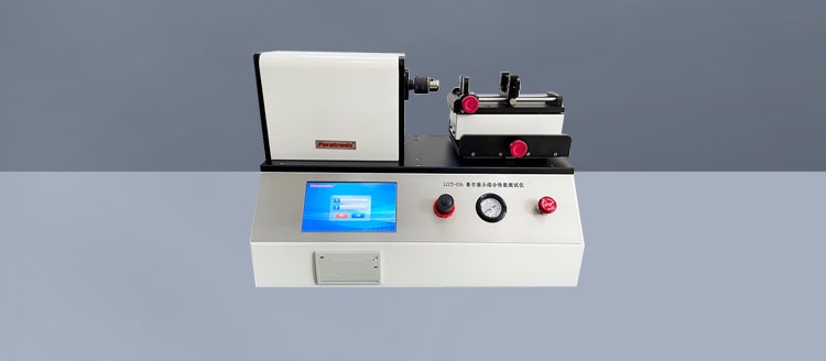
A Luer connector can appear undamaged after assembly and still develop cracks while its tapered surfaces remain under stress. A useful ISO 80369-7 test plan must therefore control how the connection is assembled, how it is conditioned, and how its performance is assessed afterward. Selecting a suitable Luer Taper stress cracking tester is one part of that plan; the reference connectors, specimen history, and acceptance rules also affect whether the results support a sound decision.
The practical starting point is to translate the applicable standard requirements into a written procedure before choosing equipment. A machine that applies force or torque accurately may still be unsuitable if its fixtures distort the connector, its reference fittings are inappropriate, or its workflow cannot reproduce the required conditioning and subsequent evaluation.
Define what the stress cracking test needs to demonstrate
ISO 80369-7 addresses small-bore connectors for intravascular or hypodermic applications, including Luer slip and Luer lock connections. Its requirements work with the common test methods in ISO 80369-20. The test plan should identify the editions and amendments used, the applicable connector requirements, and the corresponding methods. This establishes a consistent basis for testing and reporting.
Stress cracking resistance concerns the connector’s ability to withstand the stresses introduced by assembly and maintained during the specified exposure. In a tapered connection, mating surfaces generate contact pressure. A locking feature can maintain engagement and introduce additional stresses around the collar or threads. Material properties, molded geometry, and residual manufacturing stresses influence how the connector responds.
Passing a dimensional inspection does not establish resistance to stress cracking. Dimensions help define fit, but they do not fully describe material behavior under sustained assembly stress. Similarly, a connection that seals immediately after assembly has not necessarily demonstrated that it will retain the required performance after conditioning.
Keep the conclusion proportional to the test. A successful stress cracking evaluation supports the relevant connector requirement. It does not establish complete device conformity, chemical compatibility with every fluid, or acceptable performance throughout every intended use condition.
Choose specimens that represent the product being evaluated
Specimen selection should reflect the purpose of the study. Early development testing may compare resins, molding conditions, or connector geometries. Formal verification needs specimens that represent the configuration covered by the resulting claim, with a documented rationale for sample quantity and variant coverage.
Record the material grade, manufacturing lot, molding information where available, and any processing that could affect the connector. Sterilization, aging, bonding, and assembly into a finished device can change mechanical behavior or introduce stress. Testing an unprocessed molded component may be useful during development, but its results may not represent the finished product.
Product families deserve particular attention. Similar-looking connectors can differ in wall thickness, collar geometry, colorant, resin formulation, or attachment method. These differences can affect stress distribution or material response. Select representative configurations using an engineering rationale; convenience alone is a weak basis for grouping variants.
Define how specimens will be allocated across tests. Repeated mating, previous pressure testing, or earlier mechanical loading can change their condition. Use separate specimens when the method requires them, and document any permitted test sequence. Otherwise, damage created by an earlier test may be incorrectly attributed to stress cracking.
Control the mating interface and assembly conditions
The reference connector is part of the measurement system. Its geometry, material, surface condition, and suitability for the specified method affect the stress applied to the test specimen. A fitting that mates successfully is not automatically an appropriate reference connector.
Maintain identification and inspection records for reference fittings. Wear, scratches, deposits, or damaged threads can alter engagement and sealing. Replacement should follow defined condition checks and use history. Reusing a visibly damaged fitting introduces uncertainty even when the instrument itself remains calibrated.
The fixture should hold the specimen securely while preserving the intended loading path. Clamping a thin connector wall can create local damage. Misalignment can introduce bending, and a rigid mounting arrangement can transfer loads that the procedure does not intend. Support should prevent unwanted movement without changing the connector’s behavior.
For assembly, distinguish axial force from torque. Depending on the connector type and prescribed method, the procedure may require controlled application of one or both. Record the required sequence, loading rate where specified, endpoint, and handling after engagement. Manual tightening by feel makes operator technique an uncontrolled variable.
What to look for in a Luer taper stress cracking tester
Evaluate equipment against the complete procedure, including specimen mounting, assembly, conditioning, and subsequent performance checks. Some laboratories use separate instruments for these stages. That arrangement can work well when transfers preserve the required connection state and all records remain linked to the same specimen.
Measurement range deserves more attention than maximum capacity. A high-capacity instrument may provide inadequate control or resolution at the loads used for small connectors. Ask for evidence of performance in the intended operating range, including calibration coverage and measurement uncertainty where relevant.
Automation is useful when it controls meaningful sources of variation, such as assembly sequence or data capture. It cannot compensate for the wrong reference fitting or a fixture that damages the specimen. A practical equipment demonstration should use representative connector geometries and follow the proposed laboratory workflow.
Make conditioning a controlled part of the method
Separate preconditioning from the exposure performed after assembly. Preconditioning establishes the specimen’s starting state. Post-assembly exposure evaluates the connector while it is subject to the stresses created by mating. Confusing these stages changes the question the test answers.
The procedure should specify the required environment, duration, timing rules, and handling conditions from the applicable method. Identify when timing starts and how interruptions are treated. For temperature-controlled exposure, consider whether loading the chamber or placing specimens close together affects the conditions experienced by the samples.
Transfers also need defined handling. Supporting an assembly by its tubing, knocking a locking collar, or allowing an unsupported component to bend can alter the stress state. A fixture that works on the assembly instrument may need a compatible support arrangement during conditioning.
Chemical exposure requires a separate rationale. Environmental stress cracking can involve a combination of mechanical stress and contact with a substance that affects the polymer. Do not add alcohol, disinfectant, drug solution, or another medium to the standards procedure without identifying the purpose and method. An application-specific compatibility study can provide valuable evidence, but it answers a different question from an unmodified conformity test.
Set acceptance rules before testing begins
The approved protocol should connect each acceptance criterion to the applicable requirement and evaluation method. Avoid a vague instruction such as “check for cracking and leakage.” It leaves too much room for differences in inspection, timing, and interpretation.
Where the method requires a subsequent leakage assessment, define the test arrangement, medium, conditions, and acceptance limit. Visual examination can help identify damage and investigate failures, but appearance alone should not replace a required functional assessment. A connector may show little visible damage yet lose sealing performance.
If visual examination forms part of the procedure, specify lighting, magnification where required, and the areas to inspect. Record whitening, crazing, visible cracks, and leakage as distinct observations. Whitening can indicate local deformation, but it does not by itself establish the presence of a through-crack.
Sampling and retesting rules also belong in the protocol. Sample quantity should reflect the verification objective, applicable requirements, and the documented sampling rationale. A failed specimen should trigger the defined investigation process. Testing additional samples until enough pass can hide a product problem and weaken the evidence.
Investigate failures without losing the evidence
Preserve failed assemblies where practical, and photograph their condition before disassembly. Removing the reference connector may open a crack further, create additional marks, or erase clues about its origin. Record when the failure was first observed and whether it appeared during assembly, conditioning, or the subsequent assessment.
Investigate the test setup and the product together. Excessive assembly loading, damaged reference fittings, misalignment, and incorrect conditioning can invalidate a result. Material variability, thin sections, molding stresses, and processing changes can produce genuine product failures. Neither explanation should be assumed before examining the evidence.
Failure location helps direct that investigation. Damage concentrated near a clamp suggests a different mechanism from cracking along the taper or around a locking feature. Compare affected and unaffected specimens by lot, cavity, material, and processing history when those records are available. Retain individual results so that grouping does not conceal a pattern.
When comparing laboratories, align procedures before attributing differences to equipment quality. Specimen condition, reference connectors, assembly sequence, exposure timing, and evaluation settings can all affect comparability.
Build a report that supports the actual claim
A useful report links the tested configuration to the procedure and the resulting decision. Include specimen identification, processing state, standard references, equipment and reference fitting identification, conditioning records, assembly settings, individual results, and deviations. Photographs are most useful when they identify the specimen and show the relevant feature clearly.
State the scope of the conclusion precisely. If testing covered one material, one connector configuration, and one processing condition, describe that coverage. Extending the result to other variants requires a documented justification or additional evidence. Stress cracking results should sit alongside the other applicable connector and device evaluations.
Before requesting an equipment quotation, prepare a short method specification covering connector types, assembly controls, conditioning arrangements, reference fittings, and required evaluations. Paratronix Instruments Co., Ltd. manufactures packaging testing instruments and provides testing solutions; any proposed setup for this application should be assessed against that specification, with its supported functions clearly identified.
The most useful purchasing question is whether the proposed equipment can reproduce the required procedure with your specimens and produce reviewable records. Resolving that question before installation gives the laboratory a stronger starting point for consistent testing and defensible connector performance decisions.
Leave A Reply
Search by Keywords