




Recent Posts
 Axial Load, Torque, and Hold Time in Luer Connector Stress Cracking TestsOct 28, 2026
 ISO 80369-7: Planning Stress Cracking Tests for Luer ConnectorsOct 28, 2026
 What Does a Luer Taper Stress Cracking Tester Reveal About Connector Integrity?Oct 28, 2026
 Does your inclined plane friction tester meet TAPPI T 815 requirements?Oct 27, 2026
 TAPPI T 815: What to Check Before Choosing an Inclined Plane COF TesterOct 27, 2026
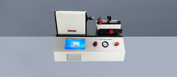
What Does a Luer Taper Stress Cracking Tester Reveal About Connector Integrity?
A connector can appear secure yet develop cracks under sustained assembly stress, potentially compromising its integrity. A Luer taper stress cracking tester helps reveal this vulnerability by assessing whether a connector withstands specified assembly, conditioning, and exposure conditions without cracking. The useful result is not simply that a part “passed.” It is evidence that a particular material, geometry, and manufacturing condition tolerated a defined challenge.
That distinction matters when evaluating medical connectors. A connection that feels tight is not necessarily resistant to cracking, and a connector that survives a cracking assessment has not automatically demonstrated leak-tightness, resistance to separation, or suitability throughout its service life. Understanding where this test fits prevents both unnecessary material changes and misplaced confidence in a single result.
The weakness can emerge after assembly, not during it
Luer connections use mating tapered surfaces to establish a connection. In locking designs, additional locking features help retain the assembled components. Bringing the parts together creates mechanical stresses in the connector body; their distribution depends on dimensions, wall thickness, material behavior, and how the connection is assembled.
For a molded plastic connector, assembly stress is only part of the picture. Residual stresses from molding may already be present. Local geometry, including transitions between thick and thin sections, can concentrate stress. Exposure to a substance that affects the polymer may further reduce its resistance to crack initiation. A component can therefore look acceptable before assembly but behave differently once these influences overlap.
Consider a transparent female connector that shows no visible defect before testing. After controlled assembly and a specified holding period, a fine crack becomes visible near the taper. That observation does not, by itself, identify the cause. It does show that the tested configuration could not tolerate the imposed conditions without damage. The investigation then needs to distinguish material susceptibility from dimensional interference, processing history, or a testing error.
What the tester actually controls—and what must be defined elsewhere
The name “stress cracking tester” can suggest a machine that measures a universal cracking strength. In practice, the equipment may be a dedicated assembly fixture, a controlled loading system, or part of a wider test arrangement. Its purpose is to make the required mechanical challenge reproducible. Depending on the method, conditioning, exposure, timing, and inspection may require separate equipment.
Before interpreting a result, the laboratory needs to establish several details:
- Which connector configuration and reference mating component are being evaluated.
- How the specified assembly force and, where applicable, torque are applied.
- What conditioning, exposure, and holding period the procedure requires.
- When and how the specimen is examined, including any specified observation conditions.
- What constitutes a failure under the applicable acceptance criteria.
These details are not administrative extras. An incorrect mating component can change the stress distribution. Uncontrolled tightening can make one specimen face a much greater challenge than another. Inspection under inconsistent lighting can turn a borderline observation into an apparent difference between batches.
For intravascular or hypodermic Luer applications, ISO 80369-7 is a relevant starting point for connector requirements, while ISO 80369-20 provides common test methods used within the series. The applicable edition, referenced method, and device-specific requirements should be checked before selecting fixtures or settings. Legacy documents may reference ISO 594; settings from older procedures should not be transferred without reviewing their applicability.
A pass supports a narrow but useful conclusion
A passing result supports the conclusion that the tested specimens met the specified stress cracking acceptance criteria under the recorded conditions. It does not establish that cracking is impossible under every assembly technique, chemical exposure, storage condition, or mating combination.
That boundary becomes especially important with environmental stress cracking. A polymer may tolerate mechanical stress in one environment but crack when stress and a particular substance act together. Where chemical compatibility is relevant, the exposure must be justified by the device’s intended use or a defined evaluation protocol. Adding a convenient solvent does not automatically make a test more representative—or more compliant.
Likewise, absence of a visible crack is not proof that the connection seals correctly. Leakage can arise from dimensional mismatch, surface defects, or inadequate engagement without obvious cracking. Conversely, a small crack may not produce an immediately detectable leak under one test condition. Stress cracking and leakage results answer different questions and should be reviewed together rather than treated as interchangeable evidence.
Where the result helps with material and design decisions
During development, a Luer taper stress cracking tester is particularly useful for comparing defined design or process changes. The comparison only becomes meaningful when other influential variables are controlled. If the resin, connector dimensions, molding conditions, and assembly method all change at once, a different outcome offers little guidance about which change mattered.
Material selection needs more than a resin datasheet
Datasheet properties can help screen candidate polymers, but they do not reproduce the stress state of a finished connector. Material grade, additives, molding history, and subsequent treatment can affect performance. A change described as “equivalent resin” therefore deserves scrutiny if the connector’s resistance to cracking is a critical requirement.
Testing finished parts helps close that gap. Where sterilization, aging, or contact with relevant substances could alter behavior, the evaluation plan should address those conditions appropriately. A satisfactory result on newly molded, untreated parts should not silently become evidence for every later condition of the device.
Geometry can outweigh an apparently stronger material
A material with attractive bulk mechanical properties may still perform poorly if the connector creates high local stress. Wall transitions, molding defects, and dimensional variation can influence where damage begins. Simply increasing wall thickness is not a universal remedy; it can also affect molding behavior and the stiffness of the assembly.
When cracks repeatedly appear in the same location, the location itself is useful evidence. Examining the part geometry and fracture origin may be more productive than immediately switching polymers. When failures appear sporadically, sample traceability becomes especially valuable: cavity, production lot, processing records, and treatment history can help organize the investigation without prematurely assigning a cause.
How to avoid misleading laboratory results
One practical mistake is to begin with specimens whose condition is poorly documented. A part damaged during handling may later be counted as an assembly-induced failure. A pre-test inspection, conducted without altering the specimen, helps distinguish existing defects from damage that develops during the assessment.
Another is treating the reference fitting as a permanent accessory that needs no attention. Its dimensions, condition, cleanliness, and suitability affect the test. Wear or surface damage can change contact conditions. The laboratory should manage it as a controlled test component, not merely a convenient connector that happens to fit.
Timing also deserves discipline. If the method specifies a holding period or an inspection sequence, shortening it because the sample “already looks fine” changes the evidence being collected. Polymer response can be time-dependent. Equally, observations made well outside the required inspection window should not be presented as though the prescribed procedure was followed.
Useful records include specimen identity, preconditioning, reference component identification, applied settings, actual timing, environmental or exposure conditions, and the observation method. Images of suspected damage can support review, but they do not replace a defined acceptance criterion. Ambiguous marks may need further examination to distinguish a crack from a scratch, molding feature, or optical effect.
Choosing equipment around the test question
For an equipment evaluation, the most useful question is not “Does this machine test Luer connectors?” It is “Can this configuration reproduce the method we need, on the connector variants we actually make?” A fixture suited to one geometry or assembly sequence may not cover another without suitable accessories or a different arrangement.
Review the required force and torque capabilities where applicable, fixture alignment, control of application, timing functions, and calibration arrangements. Confirm which tasks are automated and which remain operator-dependent. A clear display is helpful, but it cannot compensate for a poorly controlled assembly process or an unsuitable reference fitting.
Paratronix Instruments Co., Ltd. develops and supplies packaging testing instruments for pharmaceutical packaging, plastic packaging materials, and high-barrier materials. Within that broader testing context, connector assessment should be approached as a specific application with its own fixtures, methods, and evidence requirements. Any proposed equipment configuration should be checked against the intended protocol rather than assumed suitable because it belongs to a general packaging testing range.
Use cracking results alongside connection performance
A useful connector evaluation brings together complementary evidence. Depending on the applicable requirements, that may include dimensional assessment, leakage testing, resistance to separation, and evaluation of locking behavior. Each addresses a different failure mechanism. None becomes redundant simply because stress cracking specimens passed.
The strongest conclusion is therefore specific: this connector, in this material and condition, survived this defined cracking challenge. If it fails, investigate the specimen and test setup before changing the design. If it passes, check that the remaining evidence covers sealing, retention, and relevant use conditions. That is how a stress cracking result becomes a sound engineering decision rather than an isolated checkbox.
Leave A Reply
Search by Keywords