




Recent Posts
 Does your inclined plane friction tester meet TAPPI T 815 requirements?Oct 27, 2026
 TAPPI T 815: What to Check Before Choosing an Inclined Plane COF TesterOct 27, 2026
 Inclined Plane vs. Horizontal COF Testers: Which Fits Your Paper Testing Needs?Oct 27, 2026
 What Can an Inclined Plane COF Tester Tell You About Packaging Slip?Oct 27, 2026
 Which WVTR Tester Is Suitable for Pharmaceutical Packaging?Oct 26, 2026
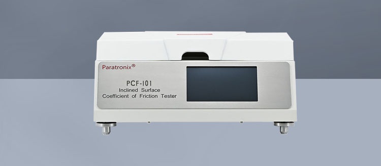
Your Inclined Surface Coefficient of Friction Tester can support TAPPI T 815 testing only when its construction, operating settings, specimen arrangement, and test procedure match the method. A tilting platform and an angle display are not enough to establish conformity. The instrument must measure the specified sliding event under controlled conditions, and the laboratory must be able to show how the result was obtained.
TAPPI T 815 addresses the static friction of packaging materials using the slide angle method. It is useful for investigating how contacting packaging surfaces resist the start of sliding. It does not, by itself, certify that a package or pallet load will remain stable during transport. Assessing your equipment therefore involves two separate questions: can it perform the method correctly, and does that measurement answer your packaging question?
What does the slide angle actually tell you?
During an inclined plane test, one specimen rests against another while the supporting plane rises. As the angle increases, the component of gravity pulling the upper assembly downhill increases. The test records the angle associated with the sliding endpoint defined by the method.
The static coefficient of friction is calculated from that angle:
Static coefficient of friction, μs = tan θ
Here, θ is the slide angle measured from horizontal. For illustration, an angle of 30° corresponds to a coefficient of approximately 0.58. This is a mathematical conversion, not a recommended acceptance limit.
A higher angle generally indicates greater resistance to the start of sliding for the tested surface combination. The result belongs to that combination and those conditions. Printed board against printed board may behave differently from the same board against an unprinted surface. Changing the coating, contact direction, moisture condition, or surface contamination can change the result.
The method measures resistance at the onset of sliding. It does not characterize the friction throughout continued movement, and it should not be treated as interchangeable with a kinetic friction measurement from another test arrangement.
Start with a documented comparison against TAPPI T 815
A supplier’s statement that a machine “supports TAPPI T 815” is a starting point. A useful assessment connects each relevant requirement in the edition used by your laboratory to the instrument configuration and written operating procedure.
This comparison should cover the apparatus, specimen preparation, conditioning, test sequence, calculation, and reporting. It should identify which requirements are handled by the machine and which depend on the operator. Automated angle calculation, for example, does not establish that specimens were cut, conditioned, or mounted correctly.
Use a controlled copy of the method as the basis for this comparison. Record the edition in your procedure and equipment assessment so that a later revision does not leave the laboratory working from mixed instructions.
A general calibration certificate cannot replace this assessment. Calibration establishes the performance of particular measurements; method conformity also depends on the apparatus and the way the test is performed.
Where the tester itself can introduce error
Smooth movement and a dependable horizontal reference
The platform should rise smoothly under the operating conditions required by the method. A sudden movement can disturb the upper assembly and initiate sliding prematurely. Mechanical vibration, looseness, or irregular drive motion can create the same problem.
The horizontal reference also matters. If the instrument starts from an incorrect zero, every reported angle can carry a systematic offset. Installation checks should address the supporting bench, instrument leveling, and the relationship between the platform position and the displayed angle.
Evaluate angle measurement across the range actually used for testing. A successful zero check alone does not demonstrate that the instrument measures correctly at higher inclinations. Display resolution also deserves careful interpretation: showing more decimal places does not establish better accuracy.
The loading assembly and specimen mounting
The upper assembly, its loading, and the specimen attachment must follow the method’s prescribed arrangement. A replacement sled that appears similar may differ in contact geometry, mass distribution, or the way it holds the material.
In the ideal friction model, mass cancels from the slide angle calculation. Real packaging surfaces can compress, deform, or change their effective contact under pressure. That is why the theoretical equation does not justify changing the loading arrangement arbitrarily.
Mounting can introduce problems. Wrinkles, loose edges, exposed adhesive, and fixtures touching the opposing surface may alter the measured resistance. The intended specimen faces should make contact without unintended restraints or interference.
A clearly defined sliding endpoint
Automatic detection can improve consistency, but only when it identifies the event required by the method. A sensor that reacts to vibration or local movement may trigger too early. A delayed response may record an angle after the assembly has already begun sliding.
For manual operation, the procedure must make the endpoint equally clear. “Record when it moves” leaves room for different interpretations of a small twitch, gradual creep, or sustained sliding. Operator instruction and functional checks should establish consistent endpoint recognition without substituting an improvised definition for the method.
Specimen preparation can outweigh an instrument upgrade
When results vary unexpectedly, the cause is not necessarily the angle sensor. Paper and board surfaces respond to moisture, and their contact behavior can change with conditioning and handling. Specimens tested immediately after arriving from storage may not behave like specimens prepared under the laboratory’s prescribed conditions.
Follow the conditioning and testing atmosphere associated with the method, and retain relevant records. Keep the interval between conditioning and testing controlled where exposure to a different environment could affect the material.
Surface selection requires equal care. Establish which faces contact each other and how their directions are aligned. For a printed carton, an outside-to-outside pairing answers a different question from an inside-to-outside pairing. A result without that information can be difficult to interpret, even if the instrument operated correctly.
Handle contact areas carefully. Finger oils, dust, coating residue, and accidental abrasion can alter friction. Specimen reuse also needs a defined rule because previous sliding may polish, scratch, or otherwise change the surface. Follow the method’s provisions for test locations and repeated measurements.
Sampling should represent the material being evaluated. Selecting only smooth, visually uniform areas can hide production variation. Where print coverage, coating application, or surface texture varies, document the sampling plan so that results describe the intended product population.
Check repeatability without mistaking it for conformity
A repeatability study helps reveal whether the combined instrument and procedure produce consistent measurements. Use specimens prepared under the same conditions, keep the contact arrangement consistent, and retain individual results rather than relying only on an average.
However, tightly grouped results can still contain systematic error. An incorrect angle reference or an unsuitable sliding trigger may produce highly repeatable measurements that do not follow the method. Repeatability and conformity provide different evidence; both are useful.
A practical investigation can separate likely causes:
- If repeated measurements vary under one operator, examine specimen variability, mounting, platform movement, and sliding detection.
- If operators obtain different results, compare handling, placement, timing, and endpoint interpretation.
- If laboratories disagree, compare method editions, conditioning, contact faces, direction, loading arrangements, and calculations.
- If a retained control material changes over time, investigate both equipment performance and changes in the control material itself.
Retained materials are useful for monitoring trends, but their surfaces may age or change during storage. They should not be treated as permanent reference standards with an assumed fixed friction value.
What conformity does—and does not—say about packaging safety
TAPPI T 815 provides a measurement method. It does not establish a universal friction value that makes every package acceptable. A laboratory can perform the method correctly and obtain a result that fails an internal specification. It can also obtain a high coefficient from a test that was performed incorrectly.
Keep the method requirement separate from the product requirement. A statement such as “tested according to TAPPI T 815” describes how the measurement was made. A pass or fail decision requires an acceptance criterion established for the application, customer agreement, or relevant packaging specification.
For stacking and handling decisions, consider what the laboratory contact represents. Testing two packaging surfaces can help compare coatings or investigate slipping complaints. A loaded pallet also responds to package geometry, compression, load distribution, vibration, restraint, and handling forces. Those effects cannot be reduced to a single static friction result.
Higher friction is not automatically preferable throughout a packaging operation. Increased resistance may help limit sliding in one situation while making feeding, separation, or positioning more difficult elsewhere. Set acceptance limits around the intended function and support them with appropriate packaging performance evaluations.
The same boundary applies to other materials. Packaging laboratories may test paperboard, plastic films, laminates, and coated structures, but a common instrument principle does not make one method suitable for every material. Choose the method around the material and measurement objective before choosing the machine.
What to request before accepting an inclined surface friction tester
Ask the supplier to demonstrate the proposed configuration against your documented method requirements. The demonstration should show specimen mounting, controlled inclination, sliding detection, angle recording, and coefficient calculation using representative materials where practical.
The accompanying documentation should identify the apparatus configuration, available operating settings, calibration coverage, maintenance needs, and any accessories required for the intended method. Clarify how software stores individual results and whether the report preserves enough information to reconstruct the test conditions.
A manufacturer such as Paratronix Instruments Co., Ltd., which supplies packaging testing instruments across several packaging sectors, can be approached with a defined material and method requirement. Request evidence for the specific proposed configuration; a broad packaging equipment portfolio does not establish the conformity of an individual tester.
For an existing machine, begin with a focused gap assessment. Compare the apparatus and procedure with TAPPI T 815, examine angle calibration and motion control, and review specimen preparation and endpoint detection. Correct the identified gaps, then document performance using representative materials. This provides a defensible basis for deciding whether the tester is suitable, whether an accessory or procedure change is sufficient, or whether replacement is justified.
Leave A Reply
Search by Keywords