




Recent Posts
 Axial Load, Torque, and Hold Time in Luer Connector Stress Cracking TestsOct 28, 2026
 ISO 80369-7: Planning Stress Cracking Tests for Luer ConnectorsOct 28, 2026
 What Does a Luer Taper Stress Cracking Tester Reveal About Connector Integrity?Oct 28, 2026
 Does your inclined plane friction tester meet TAPPI T 815 requirements?Oct 27, 2026
 TAPPI T 815: What to Check Before Choosing an Inclined Plane COF TesterOct 27, 2026
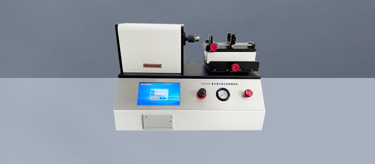
Axial load, assembly torque, and hold time determine how a Luer connector is stressed during a stress cracking test. Repeatable results depend on controlling the complete loading sequence: how the connector is seated, how torque is applied, which forces remain during the hold period, and when performance is assessed. Two laboratories can use the same nominal settings and obtain different outcomes if their fixtures, timing conventions, or assembly procedures differ.
For technical evaluators, the first decision is whether the proposed test reproduces the applicable method. A machine that reaches a specified force and torque does not, by that capability alone, establish a valid stress cracking procedure. The reference connector, specimen preparation, loading sequence, exposure conditions, and acceptance assessment must also be defined. These details determine whether a failure can reasonably be attributed to connector susceptibility or whether the setup itself needs investigation.
Establish the method before selecting the settings
For Luer connectors within its scope, ISO 80369-7 provides application-specific requirements, while ISO 80369-20 addresses common test methods for small-bore connectors. Laboratories should identify the applicable editions and read the relevant requirements together. A legacy procedure, an internal development screen, and a conformity test may have different purposes; settings should not be transferred between them without checking their basis.
A useful test specification describes the sequence in operational terms. It identifies the specimen and mating reference connector, states how they are assembled, defines the required loading and exposure periods, and explains what happens before the final assessment. It also distinguishes the duration of assembly loading from any subsequent period during which the assembled connection remains under stress.
That distinction prevents a consequential interpretation error. “Hold time” might be used informally to describe the time at an assembly force, a period after assembly, or an exposure interval. These are different operations. Maintaining the assembly force throughout a later dwell can create a different stress state from seating the connection and then removing the external force. The applicable procedure must settle that question before equipment settings are entered.
Axial load establishes seating conditions
Axial assembly force influences how the mating tapers engage. As the surfaces seat, contact generates stresses in the connector walls. Their distribution depends on geometry, material behavior, surface condition, and the mating component. Consequently, a specified axial force is a controlled assembly input; it is not a direct measurement of local stress in the polymer.
Insufficient seating force can produce a connection that does not represent the required assembly condition. Excessive force can increase deformation or damage a vulnerable feature. Either departure can obscure the comparison being made. A connector that survives an underloaded assembly has not demonstrated performance at the prescribed condition, while a failure after an unintended overload may reflect a setup error.
Evaluators should therefore examine the force trace as well as the selected value. A brief overshoot during contact may matter even when the displayed steady reading appears acceptable. Approach speed, actuator response, fixture compliance, and the transition from movement to force control can all influence that trace. The useful question is whether the equipment applies the required load within the method’s permitted conditions throughout the relevant operation.
Alignment deserves equal attention. An offset or tilted specimen can experience bending alongside axial compression. A fixture can also alter behavior by gripping a thin wall too tightly or supporting an area that would otherwise deform. Reference connector condition introduces another variable: wear, contamination, or surface damage can change seating behavior. Fixture qualification should establish alignment, restraint, and a practical basis for inspecting the mating components.
Assembly torque needs a defined load path
Where the method specifies torque, the procedure must identify the component being rotated and the component being restrained. This is especially relevant for locking designs in which a collar can move independently of the connector body. Applying torque through the wrong feature can change how the connection tightens or introduce torsional loading that the intended assembly operation does not require.
Torque also interacts with axial seating. In a threaded locking arrangement, rotation can advance the connection and alter contact forces. The outcome depends partly on thread and contact friction. Identical torque readings therefore do not guarantee identical local stresses across different materials, finishes, or connector geometries. This limits how far a laboratory can interpret torque alone as evidence of equivalent mechanical severity.
For equipment assessment, look beyond the torque range printed in the specification. The sensor should be suitable for the working range, and its installed measurement path should be understood. Friction in a holder, bearing, or transmission can affect the relationship between measured torque and torque delivered to the connection. Calibration establishes measurement performance, while verification of the assembled fixture helps establish whether the intended torque reaches the specimen.
The tightening sequence must also be reproducible. If axial force and torque are applied together, their overlap and order need to follow the method. If the operations are separate, the transition should be defined. Additional rotation after the target is reached, repeated tightening attempts, or operator correction can change the assembly history. A procedure should state how an overshoot or interrupted assembly is handled so that operators do not improvise recovery steps.
Hold time defines the opportunity for damage to develop
Polymer response can continue after assembly. Under a constrained deformation, stress may relax; under a maintained force, deformation may increase through creep. Crack initiation and growth can also depend on exposure duration and environment. An assembly that appears satisfactory immediately after tightening may therefore behave differently after the specified dwell. The hold period is part of the test condition, not simply a delay before inspection.
The timer needs an explicit starting event. Possible events include reaching the required assembly condition, completing the assembly operation, or beginning a specified exposure. The applicable method determines which event applies. Starting a timer at the first contact between components when the procedure requires completed assembly changes the effective duration, particularly when assembly takes a variable amount of time.
The equipment must also implement the correct condition during the timed period. Holding an actuator at a fixed position and actively maintaining a constant force can produce different responses as a polymer deforms. Likewise, leaving a locking connection assembled after removing the assembly tools differs from continuously applying torque. Automatic control is useful only when its behavior matches the prescribed procedure.
Temperature, conditioning, and any specified chemical exposure belong in the same interpretation. Environmental stress cracking involves the interaction of stress, material susceptibility, and a relevant environment. A mechanically loaded test without a particular exposure cannot automatically predict performance with that exposure. Conversely, adding a chemical agent to a conformity procedure without a defined basis changes the question being tested. Development studies can explore such conditions, but their results need to remain distinguishable from results obtained under the prescribed method.
Assess the stressed connection using the required endpoint
Visible cracking is useful evidence, but it should not be assumed to be the entire acceptance assessment. The applicable requirement may specify a functional evaluation after the stress cracking preparation. Where a leakage assessment is required, the pressure conditions, timing, and handling between exposure and measurement affect the result. The test plan should identify these steps before specimens are loaded.
Unspecified handling can weaken the evidence. Retightening a connection before a leakage check changes its assembly state. Disassembling it for inspection may release stress or create additional damage. A long, uncontrolled delay can also alter the condition being assessed. Follow the prescribed sequence, then use any additional inspection as supporting investigation with its timing and handling recorded.
When a specimen fails, preserve enough information to distinguish a valid product result from a procedural deviation. Crack location, assembly traces, fixture contact points, exposure records, and the final functional result provide complementary evidence. A crack beside a gripping feature warrants examination of the fixture; damage at the taper warrants examination of seating and mating geometry. Neither observation establishes a cause by itself.
What to require from a Luer taper stress cracking tester
A Luer taper stress cracking tester should be evaluated against the laboratory’s actual sequence, including the handoff to any environmental conditioning or functional test equipment. A demonstration with representative connector configurations is more informative than a list of maximum capacities. It should show whether the system can assemble the parts correctly, maintain the required conditions, and produce records that make deviations visible.
- Force and torque control: Verify performance at the intended working settings, including overshoot, stability, and the installed measurement arrangement.
- Fixture suitability: Confirm alignment, access to the correct rotating component, appropriate restraint, and compatibility with the required reference connectors.
- Sequence control: Check how loading stages overlap, what triggers the timer, and which forces or constraints remain during the dwell.
- Traceable records: Require specimen identification, settings, relevant measured values, timing, interruptions, and a clear link to the acceptance result.
Automation can reduce variation in these operations, especially when several operators or fixtures are involved. Its value depends on what is measured and retained. A stored recipe shows intended settings; a recorded trace shows how the operation proceeded. Neither replaces a controlled procedure, but together they make a disputed result easier to investigate. Manual systems can also support defensible testing when their controls and records adequately address the method.
For development work, keep the prescribed test condition as a clear baseline. Additional experiments can vary assembly force, torque, dwell, or exposure to explore sensitivity, provided the design allows their effects to be interpreted. Changing several conditions at once may reveal a vulnerable combination, but it offers limited evidence about which variable drove the response. Such studies answer a different question from a pass or fail assessment under a defined standard.
The most useful equipment evaluation ends with a reviewable test record from a representative assembly. A reviewer should be able to establish how the connector was seated, how torque was delivered, what remained applied during the dwell, when timing began, and how the connection was assessed afterward. When those points are explicit, axial load, torque, and hold time become conditions that laboratories can reproduce and compare with confidence.
Leave A Reply
Search by Keywords