




Recent Posts
 What Does a Luer Taper Easy Assembly Tester Measure?Oct 30, 2026
 Luer Easy Assembly Testing Under ISO 80369-7: Key RequirementsOct 29, 2026
 What Does a Luer Taper Resistance-to-Overriding Tester Actually Measure?Oct 29, 2026
 ISO 80369-7 Luer Lock Overriding Tests: What Your Equipment Must SupportOct 29, 2026
 Axial Load, Torque, and Hold Time in Luer Connector Stress Cracking TestsOct 28, 2026
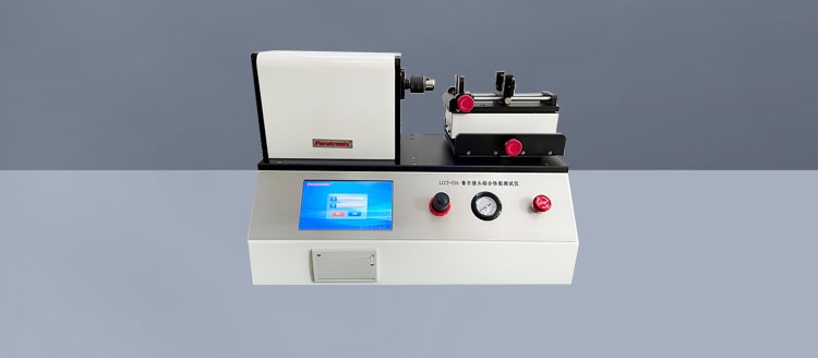
A Luer Taper easy assembly Tester measures how readily mating Luer connectors can be joined under defined test conditions. Depending on the test method and instrument, it may record the axial force, rotational torque, displacement, or a combination of these values during assembly. The resulting data helps manufacturers understand whether a connection can be made as intended and whether production variations are affecting the fit.
That matters because a Luer connection has to do more than appear compatible. A clinician or device user needs to bring two components together and assemble them without an unexpected struggle, while the completed connection must meet the separate performance requirements applicable to the device. An assembly test provides one part of that picture; it is not, by itself, proof of a leak-free or secure connection.
What Does a Luer Taper Easy Assembly Tester Measure?
At its most basic, the tester evaluates the mechanical effort or response involved in joining a male Luer connector with a compatible female connector. The exact measurement depends on whether the connection is a slip type, which is pushed together, or a lock type, which also involves engaging a locking feature through rotation.
An instrument may measure a continuous force or torque profile, report a maximum value, or apply specified assembly conditions and record whether the connection can be assembled as required. These approaches are related, but they do not answer exactly the same question. A force profile describes what happened during movement; a pass-or-fail assessment determines whether the specimen met the conditions defined by the selected procedure.
Axial assembly force
Axial force is the pushing force applied along the centerline of the two connectors. It is relevant when bringing mating tapered surfaces together, particularly during push-on assembly. Depending on the test setup, the result may be expressed as the peak force reached during the movement or as force at a specified position.
An unexpectedly high reading may point to dimensional variation, surface friction, misalignment, or another condition that makes mating more difficult. A low reading is not automatically better: the connection still needs to perform adequately in separate tests appropriate to its intended use.
Assembly torque
For threaded or locking connections, torque describes the rotational effort applied while engaging the lock. A tester equipped to measure torque can show whether turning resistance remains relatively consistent or rises sharply at a particular stage.
That distinction is useful during development. Two connectors might reach a similar maximum torque, yet one may engage smoothly while the other catches or binds. A full torque-versus-angle curve, where available, can reveal behavior that a single peak value would hide.
Movement and the force profile
Some test systems also record axial displacement, rotational angle, or both. These measurements give context to the force and torque data: they show not just how much effort occurred, but when it occurred during assembly.
For example, a force increase at initial contact may suggest a different issue from a rise near the end of travel. Engineers can use this information to investigate alignment, taper geometry, locking features, or surface condition. The curve alone does not identify the cause, however; the components and test setup still need to be examined.
How an Easy Assembly Test Is Performed
The procedure starts with a defined pair of mating components. Depending on the purpose of the assessment, one may be a production connector and the other a specified reference connector, or the test may use two components intended to be supplied together. The choice matters because the mating part influences the result.
The connectors are secured in fixtures that support the intended direction of movement without unnecessarily deforming them. The operator then aligns the specimens and sets the relevant conditions, such as movement speed, applied force, rotation, and the endpoint of the test. The tester brings the connectors together while measuring or controlling the parameters required by the method.
Afterward, the result may be reviewed as a numerical value, a force or torque curve, a pass-or-fail observation, or a combination of these. The report should identify the specimens, mating connector, equipment, settings, and test method so that another person can understand what the result represents.
It is tempting to treat an assembly value as a universal property of a connector. In practice, it belongs to a particular test configuration. Change the mating component, fixture alignment, speed, or endpoint, and the result may change as well.
Which Standards May Apply to Luer Connector Testing?
For many medical-device applications, the relevant framework is the ISO 80369 series for small-bore connectors. ISO 80369-7 addresses connectors for intravascular or hypodermic applications, including Luer connectors, while ISO 80369-20 describes common test methods used across the series. The applicable part, edition, and test method should be confirmed for the device and market concerned.
These documents cover more than one aspect of connector performance. An easy assembly assessment should be considered alongside the other requirements applicable to the product, rather than treated as a substitute for them. Regulatory expectations and the device’s intended use may also influence the overall verification plan.
Check the exact method before setting acceptance criteria. A standard-defined procedure may specify how to prepare specimens, which reference connector to use, how to apply loads, and how to judge the outcome. A development test that records a useful force curve is not necessarily equivalent to a standards-based conformity test.
Likewise, a test system may support a particular method only when it has the correct fixtures, measuring capability, software configuration, and documented procedure. The presence of an assembly test function alone does not establish compliance.
Easy Assembly Is Only One Part of Connector Performance
People researching a Luer Taper easy assembly Tester are often trying to answer a broader question: “Will this connection work reliably?” Assembly behavior is important, but it should be interpreted alongside other evaluations.
A connector that assembles easily may still fail a leakage or retention assessment. Conversely, a connection that passes those tests may feel difficult to assemble. Reviewing the results together gives a more useful view of the design than optimizing any one measurement in isolation.
What Can Influence the Measurement?
When results vary, the connector design is only one place to look. The measurement is also affected by the materials, mating parts, and way the test is carried out.
- Connector dimensions and surface condition: Variations in tapered surfaces, locking features, or surface finish can change contact and friction during assembly.
- Material behavior: Flexible components may deform differently from rigid ones, affecting both the force curve and the final position.
- Mating component: A reference connector and a production counterpart may produce different results. Their identity and condition should be recorded.
- Alignment and fixturing: Off-axis loading or a fixture that distorts the specimen can introduce resistance that does not reflect normal assembly.
- Test speed and endpoint: Changing how quickly or how far the connector moves can alter the measured response.
- Specimen history: Previous assembly, handling, conditioning, or damage may affect subsequent measurements.
Controlled preparation is especially important when comparing production batches or evaluating a design change. If several conditions change at once, it becomes difficult to tell whether a different reading comes from the product or the test itself.
How Should the Results Be Interpreted?
Begin with the purpose of the test. For a standards-based assessment, compare the observations with the criteria in the applicable procedure. For internal development work, define in advance which values or features of the curve matter and why they are relevant to the intended assembly.
Consider both the typical result and variation between specimens. A group of connectors with similar average values but occasional sharp force peaks may deserve closer investigation. Those outliers could be associated with part variation or with inconsistent positioning in the fixture; either explanation is worth checking before drawing a conclusion.
It is also useful to compare like with like. A peak force measured with one mating connector cannot automatically be compared with a result obtained using another connector or a different movement speed. Keep the test conditions with the data, not in a separate note that may be lost later.
Finally, avoid converting a laboratory number directly into a claim about user comfort or clinical usability. Instrumented testing provides repeatable mechanical information under defined conditions. Understanding how people actually assemble a device may require a separate usability evaluation appropriate to the product.
Where Is This Test Useful?
During product development, assembly measurements help teams compare design iterations and investigate changes in taper geometry, materials, or locking features. The data can support decisions before a design is finalized, particularly when assembly behavior must be balanced against sealing and retention performance.
In manufacturing quality control, a consistent method can help identify shifts between batches or investigate a reported assembly issue. The value lies in using a controlled comparison: the same specimen preparation, mating component, fixture, and test settings make trends easier to interpret.
Testing can also be relevant when a connector is supplied as part of a broader medical device or packaging system. In such cases, the connector assessment should be planned alongside the other tests needed for the finished product. Paratronix Instruments Co., Ltd. focuses on packaging testing instruments and solutions for sectors including pharmaceutical packaging; the appropriate test approach depends on the component, the applicable method, and the performance question being asked.
Choosing an Assembly Testing Approach
Start by identifying whether the immediate need is exploratory development, routine quality monitoring, or a formal assessment against a specified method. That decision affects the fixtures, controls, measurement range, data recording, and reporting functions required.
Ask whether the equipment can accommodate the actual connector geometry without distorting it, measure or control the required axial and rotational actions, and retain enough information to reproduce the test. If a standard is involved, review its current requirements against the complete proposed configuration—not just the instrument name.
The most useful result is not necessarily the most elaborate graph. It is a result that answers a clearly defined question, was obtained under documented conditions, and can be interpreted alongside the other evidence needed for the connection. That is what makes easy assembly testing valuable: it turns the simple act of joining two components into information a development or quality team can use.
Leave A Reply
Search by Keywords