




Recent Posts
 Which Features Have the Greatest Impact on Puncture Force Tester Cost?Sep 17, 2026
 Bone Screw Torsion Tester Requirements for ASTM F543 Mechanical TestingSep 17, 2026
 Self-Tapping Screw Tester Metrics for Torque, Insertion, and Pull-Out TestingSep 17, 2026
 Non-Destructive Sealing Tester Methods for Blister Pack Integrity ControlSep 17, 2026
 ASTM and ISO Requirements for Plastic Film Puncture Force Test Method ValidationSep 16, 2026
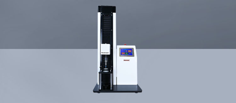
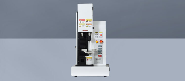
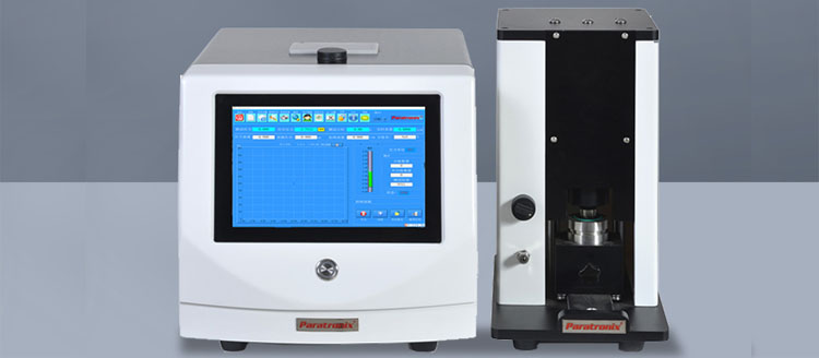
A Bone Screw Torsion Tester used for ASTM F543 work must do more than rotate a specimen until it breaks. It must apply torque in a controlled, traceable manner while holding the screw on the correct axis, capturing the required response, and preserving enough detail for a reviewer to understand how the result was obtained. A high torque value from an unstable setup is not a reliable mechanical result.
For bone screw evaluation, the tester should be selected around the specific ASTM F543 method being performed, the screw design, the expected torque range, and the documentation required by the quality system. The same equipment may be capable of measuring insertion torque, removal torque, and torsional strength, but these are not interchangeable tests. Each uses different fixtures, specimen conditions, endpoints, and result interpretation.
Start with the ASTM F543 Test Objective
ASTM F543 covers test methods and specifications associated with metallic medical bone screws. Within its mechanical testing framework, torsional testing is generally used to determine whether the screw can withstand rotational loading without unacceptable failure. The test is relevant because bone screws are driven by rotational torque during implantation, yet the screw must retain adequate structural integrity after placement.
A torsional strength test normally applies increasing rotation to a screw until failure or until the method-defined endpoint is reached. The test output may include the maximum torque reached, the torque-rotation relationship, the angle of rotation at failure, and observations about the failure location or mode. These details matter because two screws can show similar peak torque while failing in very different ways. A brittle fracture near the head, a stripped drive recess, and yielding along the shaft may have different implications for design review and manufacturing investigation.
Before choosing equipment, define which question the test must answer:
- Can the screw withstand torsion during intended use?
- Is lot-to-lot production consistent?
- Did a material, heat-treatment, coating, or machining change affect mechanical behavior?
- Does the screw drive feature transmit torque without damage?
- Does the test support design verification, process validation, incoming inspection, or complaint investigation?
The purpose determines the necessary measurement range, recording rate, fixture design, data review process, and test report format. Treating all of these as a simple “maximum torque” measurement is a common source of weak data.
Torque Capacity Must Fit the Expected Failure Range
The torque transducer is the measurement core of a Bone Screw Torsion Tester. It should cover the expected test range without placing routine results at the very bottom or near the maximum end of its usable capacity. A transducer selected only because it has a high maximum torque rating may provide insufficient resolution for smaller screws. Conversely, a low-capacity sensor may overload during testing of larger or stronger products.
The practical selection question is not simply, “What is the strongest screw we make?” It is, “At what torque values will this test method generate useful data, including the lower end of the product family?” If one platform must cover a wide product range, interchangeable or appropriately selected torque sensors may be more suitable than forcing all specimens onto one measurement range.
Resolution and accuracy should be considered separately. Resolution affects how finely changing torque is displayed and recorded. Accuracy addresses how closely the measurement reflects the actual applied torque. Both influence the ability to distinguish a normal production variation from a meaningful shift. A system should also support calibration traceability and a defined verification process, because torque data used in quality records must remain defensible over time.
Axis Alignment Is a Mechanical Requirement, Not a Fixture Detail
A bone screw is a slender component with threads, a head or drive interface, and sometimes a narrow transition between these areas. Small fixture errors can introduce bending or side loading during torsion. That can change the apparent failure torque, move the fracture location, or create a result that does not represent pure rotational loading.
The tester should hold the screw so that the longitudinal axis of the specimen is aligned with the rotational axis of the machine. The driven end must engage the screw head, recess, or designated interface without slippage. The opposite end must be restrained in a manner consistent with the applicable method and intended test condition.
Good alignment is usually supported by a rigid fixture structure, concentric adapters, repeatable specimen location, and minimal clearance between mating components. Fixture repeatability becomes especially important when comparing product lots or evaluating small changes in screw geometry. A fixture that is adjusted differently by each operator can introduce more variation than the product being evaluated.
Do Not Clamp Threads Carelessly
Thread damage caused by an unsuitable clamp can distort the test. Excessive clamping force may notch the thread, while inadequate grip can allow specimen slip. Either condition can produce an artificial failure mode. The fixture contact area, jaw geometry, and clamping procedure should be chosen to secure the screw without creating unintended damage.
For certain configurations, it may be more appropriate to grip a designated portion of the screw, use a custom collet, or incorporate a test block that represents the required holding condition. The correct arrangement is driven by the test method and product design, not by what is easiest to mount on a universal torsion fixture.
Controlled Rotation and Data Acquisition Define Test Quality
Torsional results depend on how the torque is applied. A tester should provide controlled rotational motion and maintain a stable test rate throughout the relevant portion of the procedure. Sudden acceleration, speed fluctuation, or manual rotation can alter the torque curve and make comparison between tests less meaningful.
The equipment should record torque continuously throughout the test rather than only displaying a final maximum value. A torque-versus-rotation curve is often more informative than a single peak number. It can reveal early drive-interface damage, progressive yielding, abrupt fracture, fixture slip, or irregular engagement before peak torque is reached.
Sampling behavior deserves attention. If the acquisition rate is too low, a rapid fracture event may be represented by only a few data points, making peak detection and curve interpretation less reliable. The system should capture the response at a rate appropriate for the selected rotational speed and expected failure behavior. This is particularly relevant when testing small screws, where the failure event can occur quickly.
Fixtures Must Match the Screw and the Test Method
A torsion tester is only as suitable as its fixturing. Standard grips may be adequate for early feasibility work, but controlled ASTM F543 testing often requires fixtures designed for the screw family and the specified loading arrangement. This does not always mean that every screw size needs a completely separate fixture. A modular system with controlled adapters can be effective when it preserves concentricity, engagement depth, and rigidity.
Drive engagement is a frequent concern. Hexalobular, hexagonal, cruciform, slotted, and proprietary recesses transfer torque differently. The mating driver must fit correctly and should not bottom out, rock, or engage only a small portion of the recess. A poorly matched driver can strip the head before the screw shaft reaches its actual torsional limit. That may be a valid result only if the drive interface is intentionally part of the test objective; otherwise, it is a fixture-induced artifact.
The fixture should also allow the operator to confirm insertion depth and orientation consistently. A simple depth stop or locating feature can reduce setup variation. When a test requires a screw to be placed into a material or test block, that setup must be controlled as carefully as the tester itself. The condition of the block, pilot hole preparation, insertion depth, and interface geometry can affect the measured torque response.
Separate Torsional Strength from Insertion and Removal Torque
A common mistake is to assume that a tester used for screw insertion torque automatically provides a torsional strength result. Insertion torque measures resistance while driving a screw into a specified medium or test block. Removal torque measures resistance while reversing the screw from that medium. Torsional strength evaluates the screw’s resistance to twisting under the defined torsional loading arrangement.
These tests may share a motor, torque sensor, and data system, but they answer different questions. Insertion and removal testing is strongly influenced by thread geometry, pilot hole condition, material density, insertion depth, and insertion procedure. Torsional strength testing is more focused on the component’s response to rotational loading and the performance of its head, shaft, and drive interface under the test setup.
When equipment is intended to perform more than one ASTM F543-related procedure, the changeover process needs to be documented. Operators should not rely on visual judgment to decide that an insertion fixture and a torsion fixture are “close enough.” Each configuration should have defined fixtures, software settings, setup instructions, and acceptance logic.
Software Should Support Reviewable, Not Just Readable, Results
A digital display is useful during testing, but quality documentation needs more than a number on a screen. The software should associate the test result with specimen identification, operator information, test configuration, date and time, torque sensor identity, and the selected method or procedure. It should preserve the raw or curve data needed to investigate an unusual result.
For controlled environments, access control and auditability may also be necessary. The appropriate level depends on the organization’s quality procedures and how the test data is used. At a minimum, it should be possible to determine which test setup produced a given result and whether the result was changed, repeated, or invalidated for a documented reason.
Automatic pass/fail evaluation can be useful, but it should not replace technical review. A specimen may meet a minimum torque criterion while exhibiting an abnormal curve shape, premature recess deformation, or inconsistent failure location. Those conditions can indicate a developing process issue before a formal acceptance limit is crossed.
Build Method Controls Around the Instrument
Even a capable tester cannot compensate for an incomplete procedure. The method should define specimen conditioning where relevant, the number of specimens, fixture selection, drive engagement, rotational direction, test rate, stop condition, data to be reported, and rules for handling invalid runs. It should also describe what constitutes an equipment-related anomaly, such as visible slippage, fixture breakage, or sensor overload.
Pre-test inspection is worthwhile. Check that the screw is free from visible handling damage, the driver is not worn, the fixture is clean, and the selected torque capacity is appropriate. After testing, record the failure mode rather than storing only the peak torque. A fracture at a consistent design location may be expected; a shift in failure location across a production lot may justify further review.
Routine system checks should include torque verification, fixture condition, alignment confirmation, and review of test curves. Wear in a driver bit or clamping element may not be obvious during a basic functional check, yet it can alter the load path enough to affect results.
What to Confirm Before Buying or Qualifying a Tester
For ASTM F543 mechanical testing, the best equipment decision usually begins with representative screws and the actual test procedure, not a generic equipment specification sheet. Ask the supplier to demonstrate the complete setup with the relevant screw size, head style, and expected endpoint. Review the torque curve, not only the displayed maximum value.
- Can the torque measurement range cover the full product family with useful resolution?
- Can the machine control and document the required rotational motion?
- Is angular displacement captured if the procedure requires torsion behavior beyond peak torque?
- Will the fixture maintain coaxial alignment and repeatable drive engagement?
- Can the system prevent or identify slip, overload, and invalid runs?
- Can reports include the configuration and traceability information needed for internal review?
- Are fixture changes controlled well enough to support repeatable results across operators and shifts?
A packaging-testing supplier’s standard product range may not automatically translate to orthopedic mechanical testing. Paratronix Instruments Co., Ltd. develops packaging test systems for pharmaceutical packaging, plastic packaging materials, and high-barrier materials. That background can be relevant where controlled force, torque measurement, fixtures, and traceable test data are needed, but an ASTM F543 bone screw application requires confirmation that the tester configuration, sensor range, specimen holders, and software workflow are designed for the orthopedic test method rather than adapted only at a basic level.
The reliable path is to qualify the complete test system: instrument, transducer, fixture, driver, software method, operator setup, and reporting process. That approach produces results that are more likely to represent the screw’s actual torsional performance and more useful when a quality or safety decision depends on them.
Leave A Reply
Search by Keywords