




What Is A Bone Screw Performance Tester?
A Bone screw performance tester is a mechanical testing system used to apply controlled rotational or axial loads to bone screws and record their response. Depending on its configuration, it can measure torque, angular displacement, force, and displacement during defined test procedures. The resulting data help manufacturers and laboratories compare designs, monitor production consistency, and investigate mechanical behavior. The tester is a measurement tool; meaningful conclusions also depend on the specimen, fixture, test medium, and procedure.
ASTM F543 is a standard specification and set of test methods for metallic medical bone screws. Its test methods address properties including torsional performance, driving torque, axial pullout strength, and self-tapping performance. A buyer should obtain the applicable published edition and review its scope, apparatus, specimen preparation, calculation, and reporting requirements. Different screw designs and intended uses may require additional standards or justified modifications, so a reference to ASTM F543 alone does not establish overall device suitability.
These tests answer different engineering questions. Torsion testing examines how a screw responds to twisting; insertion and removal testing characterize driving behavior; pullout testing measures resistance to axial extraction from a specified medium. Self-tapping testing examines the force associated with starting a screw in a prepared test block under specified conditions. Results are not interchangeable, and a high value in one test does not by itself demonstrate clinical performance or predictable fixation in every patient.
ASTM F543 Test Methods And Measurements
In a torsion test, the screw is secured in a suitable holding arrangement and driven about its longitudinal axis while torque and angular displacement are recorded. The procedure can determine characteristics such as torsional yield strength, maximum torque, and angular displacement at failure, as applicable to the selected method. Grip design, engagement length, driver fit, and alignment matter because slippage or damage at the clamping point can influence the measured response and obscure the location of failure.
Insertion and removal tests measure torque as a screw is driven into and subsequently removed from a defined test material. A torque-versus-angle or torque-versus-depth trace can reveal changes that a single peak value would conceal. Test-block material, pilot-hole dimensions, insertion depth, driving speed, and any applied axial force should be controlled and recorded. Comparisons are most useful when these conditions are consistent; results from different substrates or preparation methods should not be treated as directly equivalent.
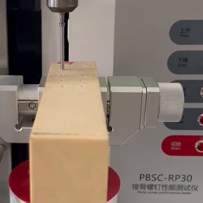
For axial pullout, a screw is placed in a specified test medium and extracted along its axis while force and displacement are measured. Peak force is commonly used to characterize pullout resistance under the chosen conditions. In a self-tapping test, controlled rotation and axial loading are used to evaluate the force needed for the screw to advance into a prepared material. Follow the applicable standard for specimen setup and calculations, and distinguish a test-block result from performance in living bone.
Tester Types And Operating Principles
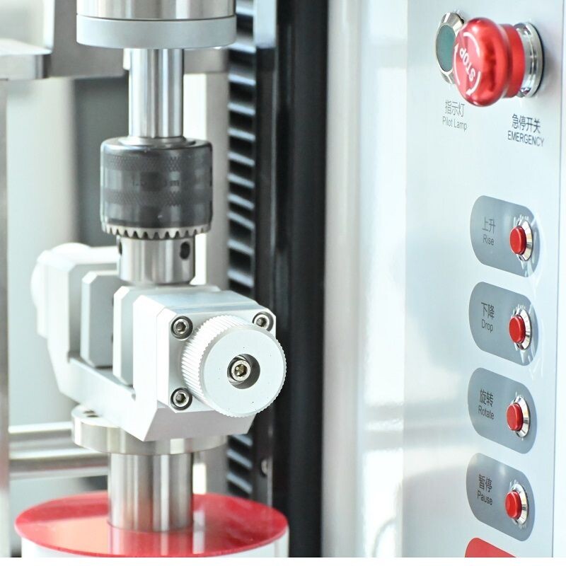
A torsion-focused system applies rotation through a drive mechanism and measures reaction torque with a calibrated transducer. Its useful configuration depends on the expected torque range, screw geometry, driver interface, and required angular measurement. A dedicated axial machine applies tensile or compressive force through a load frame and load cell, making it relevant to pullout or other axial loading procedures. Both arrangements require fixtures that hold specimens securely without introducing unintended bending or damaging the screw before testing.
A combined or multipurpose system can support rotational and axial procedures when equipped with suitable drives, sensors, controls, and fixtures. That flexibility can reduce equipment duplication, but a shared frame does not automatically provide every function required by ASTM F543. Confirm whether rotation and axial motion can be controlled as the intended method requires, whether channels can be recorded together, and whether the system can accommodate the full range of screw sizes and test blocks in the laboratory.
During operation, the controller applies the selected motion or load profile while sensors collect the response. Software then displays and stores the trace and calculates selected results from the measured data. Sampling rate, sensor capacity, resolution, and data processing affect what the operator can observe, especially around rapid changes or failure. Ask how raw data are retained, how calculations are defined, and whether exported results can be reviewed independently as part of the laboratory's quality system.
Applications Standards And The Paratronix Option
Orthopedic implant manufacturers use screw testing during design development, design verification, process changes, and production monitoring. Contract laboratories may need broader fixture coverage to handle multiple customers and geometries, while research groups may use the equipment to compare thread forms or investigate test methods. The appropriate test plan depends on the device and the question being asked. Define acceptance criteria and sample selection before testing, rather than treating an individual measurement as a complete product assessment.
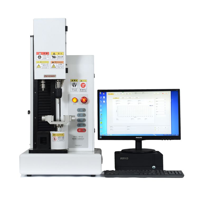
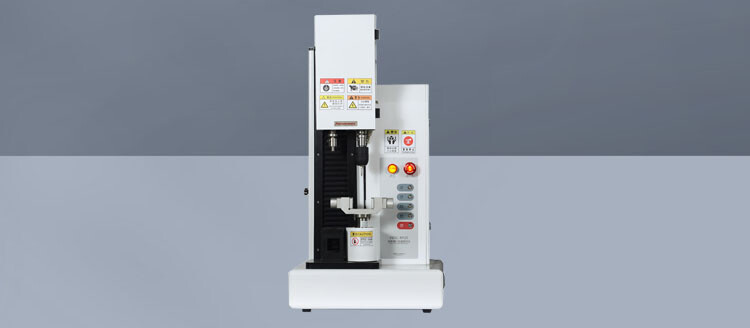
For purchasers reviewing a Bone screw performance tester, paratronix lists the PBSC-RP30 Bone Screw Performance Tester as a related product. Its wider portfolio includes torque testers, multipurpose testers, leak testers, and medical packaging physical performance testers, which may be relevant to organizations assessing different equipment needs. Request the PBSC-RP30's current specifications, available fixtures, software functions, calibration documentation, and test-method coverage before determining whether a proposed configuration fits a particular ASTM F543 procedure.
ASTM F543 data can support a broader technical documentation strategy, but market access requirements depend on the device, jurisdiction, intended use, and applicable regulatory pathway. Laboratories may also work within a quality management or competence framework appropriate to their role; equipment alone does not confer accreditation or regulatory clearance. Identify the standard edition and any purchaser-specific requirements in the test plan, and document deviations so reviewers can understand the limits of each result.
Selection Installation And Quality Control
Start selection with the screw family and the tests to be performed. Establish expected force and torque ranges, specimen lengths, driver interfaces, test-block dimensions, required travel, and available laboratory space. Choose sensors whose calibrated ranges cover the measurements of interest without relying only on their maximum capacities. Ask the supplier to demonstrate the proposed fixture and measurement sequence on representative specimens, including how the system handles the transition from insertion to removal or pullout where relevant.
Before routine use, install the tester on a suitable stable surface, connect the specified utilities, and verify that guards, emergency stops, and operator access meet local safety requirements. Confirm load and torque calibration, motion settings, alignment, data acquisition, and the condition of drivers and grips. Establish a documented procedure for specimen identification, block preparation, setup checks, and data review. A trial run with representative parts can expose interference, fixture slip, or unsuitable sensor selection before formal testing begins.
A useful report records the screw identification, standard edition, test method, specimen quantity, test medium, preparation, fixture, loading conditions, results, and any deviations. Preserve relevant raw curves alongside calculated values and failure observations. Schedule calibration and preventive maintenance according to the equipment maker's recommendations, laboratory procedures, and usage; check fixtures and drivers for wear between runs. Investigate unusual trace shapes or shifts in control results before attributing differences solely to the screw design.
Total Ownership Cost And Future Trends
The purchase price is only one part of total ownership cost. Include the frame, torque and force sensors, grips, drivers, test-block fixtures, software options, installation, training, and initial calibration in the comparison. Ongoing costs can include recalibration, replacement drivers, test blocks, maintenance, software support, and operator time. Ask which items are included in the quotation and which are optional, and check whether adding a new screw size or test method will require further hardware.
Estimate return on investment against the laboratory's actual workload. Compare external testing fees and turnaround with internal labor, consumables, equipment depreciation, maintenance, and quality oversight. Consider whether faster access to traces would help engineering teams investigate design changes or production variation, while allowing for the time needed to validate methods and train staff. For intermittent testing, outsourcing may remain practical; for recurring work, an in-house system may offer greater scheduling control.
Future purchasing decisions should account for evolving screw designs, digital records, and more demanding traceability expectations. Configurable fixtures, accessible raw data, and documented software controls can help a laboratory adapt as its test program changes, subject to the capabilities of the selected system. Review standard revisions and internal procedures periodically, and reassess equipment after meaningful changes to specimens or methods. To evaluate a proposed configuration, provide paratronix with representative drawings, target tests, expected ranges, and reporting needs.
Search by Keywords