




What Is A Self Tapping Screw Tester?
A Self Tapping Screw Tester is a measurement system used to evaluate how a screw forms or engages threads and withstands mechanical loading. Depending on its configuration, it can record insertion torque, removal torque, axial force, pull-out strength or torsional failure. The equipment typically combines a drive or loading mechanism, calibrated sensors, a controller, software and fixtures that hold the screw and test material in a defined position.
Self-tapping screws are used in materials ranging from sheet metal and polymers to bone. Their performance depends on screw geometry, material, surface condition, pilot-hole dimensions and the properties of the receiving material. A useful test therefore evaluates the screw and the test substrate together. A torque value alone cannot establish whether the joint will remain secure in every application or whether an implant is clinically suitable.
Typical users include fastener manufacturers, medical device developers, incoming inspection teams, research laboratories and organizations comparing alternative designs or suppliers. Engineering teams may use the equipment during development to screen thread geometry, while quality teams use controlled procedures to monitor production consistency. The appropriate test plan depends on the product specification, intended use, applicable standard and the decisions the resulting data must support.
Testing Principles And Key Measurements
During insertion testing, a motor rotates the screw at a controlled rate while a torque sensor records resistance against rotation or time. Some systems also measure axial load and displacement. The resulting curve can reveal the onset of thread formation, peak insertion torque and changes as the screw advances. Test speed, axial feed, driver engagement and substrate preparation must be controlled before results from different samples are compared.
Removal testing reverses the drive after insertion and measures the torque needed to loosen the screw. Pull-out testing applies an axial tensile force to an inserted screw and records the force and displacement until a defined endpoint or failure. These measurements describe different failure mechanisms: high insertion torque does not necessarily imply high pull-out resistance, and a strong initial fixation does not by itself demonstrate long-term performance.
Torsion testing can assess resistance to twisting under specified conditions, including maximum torque and angular displacement at failure when required by the method. Depending on the setup, failure may occur in the screw, the substrate, the driver interface or the fixture. Retain the full measurement curve and document the failure location; a single peak value can conceal driver slip, fixture movement or inconsistent specimen alignment.
Main Tester Types And Configurations
A torque-focused tester is suited to controlled insertion and removal measurements when axial tensile testing is not required. Buyers should distinguish a simple torque reading device from a system that also controls rotation, records a curve and manages test parameters. The necessary configuration depends on whether the objective is a quick production check, a repeatable design comparison or documented testing against a formal procedure.
A multipurpose mechanical tester may support axial pull-out, compression or other mechanical tests when equipped with appropriate load cells, grips and software. Combining torque and axial measurements may require additional modules or fixtures; it should not be assumed from the machine category alone. Confirm that the instrument can apply the prescribed loading direction, speed and travel while maintaining alignment throughout the relevant test.
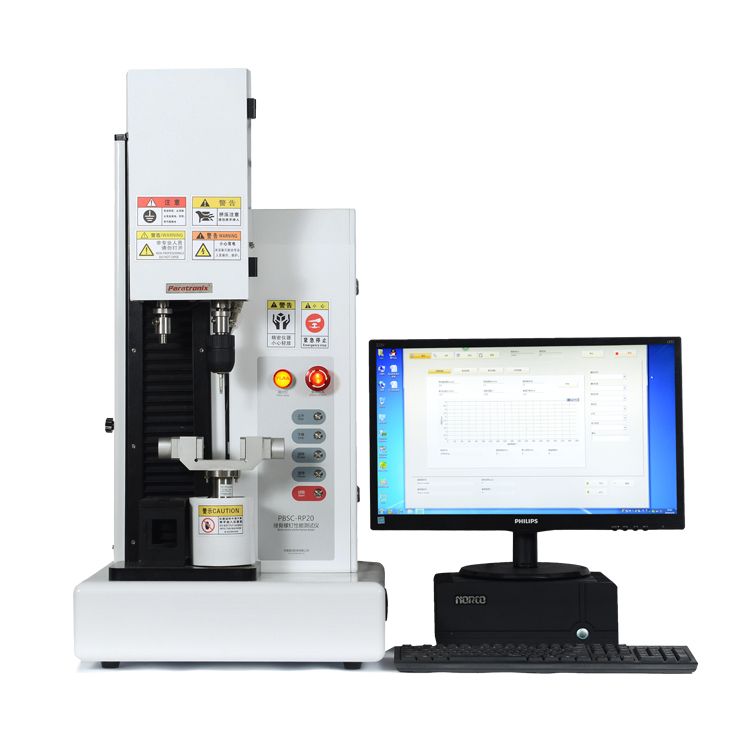
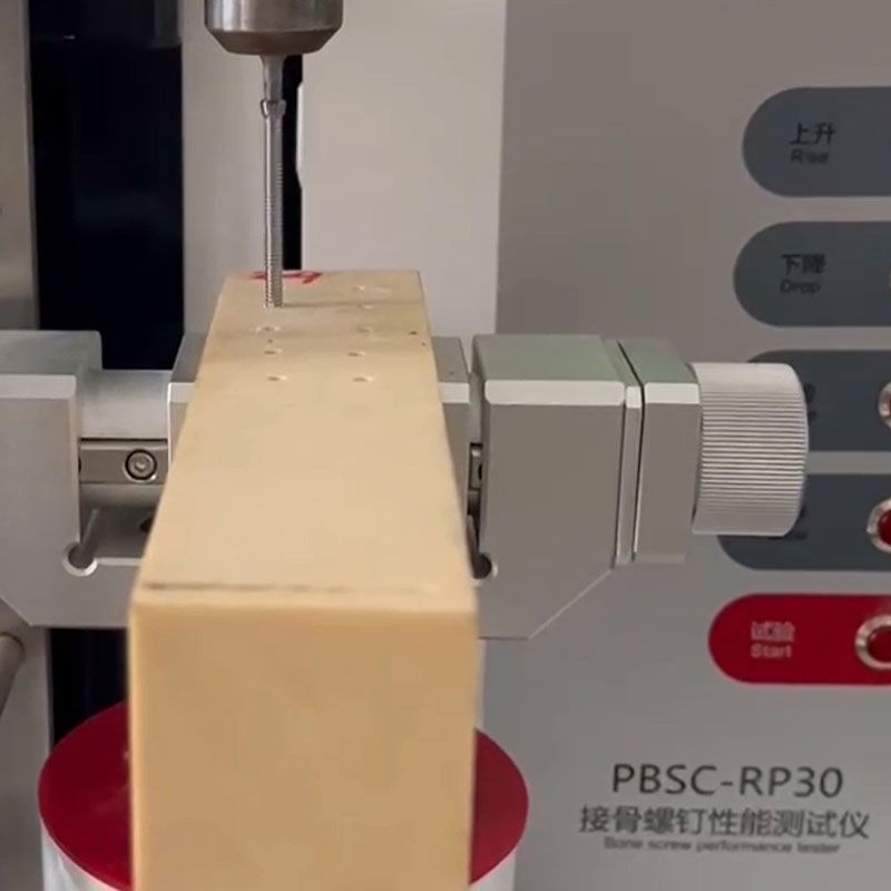
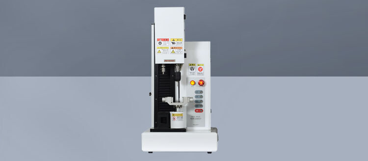
Specialized bone screw systems address medical device test arrangements, where the substrate, insertion procedure and specimen geometry are particularly important. paratronix lists the PBSC-RP30 Bone Screw Performance Tester as a related product. Buyers should request its current specifications and confirm which torque, insertion and pull-out functions, fixtures and standards are supported before selecting it for a specific application. A product name alone does not establish method compliance.
Standards And Application Requirements
For metallic medical bone screws, ASTM F543 includes test methods addressing properties such as torsional performance, insertion and removal torque, and axial pull-out strength. ASTM F1839 addresses rigid polyurethane foam used as a standard material for testing orthopaedic devices. These documents serve different purposes: using a standardized foam does not automatically make a complete screw test compliant with a particular method.
Industrial fasteners may be governed by different product specifications and test methods. For example, ISO 2702 addresses mechanical and functional properties of specified heat-treated steel tapping screws, subject to its stated scope. Confirm the screw material, size, application and test conditions before relying on any standard. The latest applicable edition, contract requirements and relevant regulatory expectations should be checked directly with the standards publisher and responsible quality team.
For medical device development, results may contribute to design verification or a regulatory submission, but a tester does not independently establish product approval. Define acceptance criteria from the applicable specification and risk assessment, and document any deviations. paratronix supplies torque and multipurpose testing equipment; discuss the intended method and evidence needs with the supplier to determine whether a proposed configuration can perform the required measurements.
How To Select A Tester
Start with a written test matrix covering screw sizes, materials, pilot holes, substrates, required measurements and expected force and torque ranges. Include both anticipated peaks and low-level measurements so that sensor selection is not based only on maximum capacity. Ask for the specified accuracy over the actual working range, as well as resolution, loading speed, travel and sampling capabilities relevant to the curves you need.
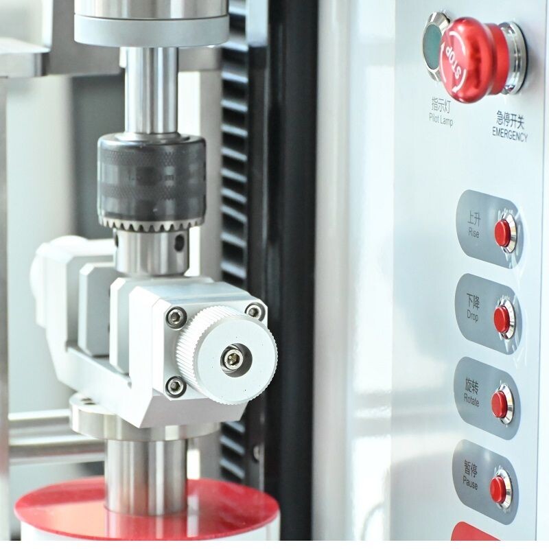
Examine the mechanical interfaces closely. Driver bits must engage the screw head reliably, and substrate holders should resist movement without damaging the test specimen. For pull-out, check that the grip transfers force along the intended axis and accommodates the screw geometry. Request drawings or a demonstration using representative samples, especially for small screws, unusual head shapes or constrained medical device test blocks.
Review software and service requirements alongside hardware. Useful capabilities can include parameter control, curve storage, specimen identification, exportable raw data and documented calibration support. Where traceability or electronic records are important, verify the actual access controls and audit features rather than assuming they are included. Request a quotation that identifies included sensors, fixtures, installation, training, warranty terms and optional modules.
Test Workflow And Quality Control
Begin by approving a method that specifies specimen preparation, substrate identification, pilot-hole dimensions, insertion depth, drive speed and any required axial loading. Record screw batch, substrate batch and environmental conditions when relevant. Use representative samples and an appropriate sample count established by the quality or engineering team. Randomize or otherwise control test order when comparing designs to reduce bias from changes in operators, materials or equipment setup.
Before testing, inspect bits and fixtures for wear, verify alignment, check sensor zero and confirm calibration status. Secure the test block, engage the driver fully and run the specified insertion sequence. For removal or pull-out, follow the method's timing and setup requirements without disturbing the specimen unnecessarily. Record any slip, fracture or abnormal movement, and retain raw curves alongside calculated results and observations.
Investigate unexpected results before excluding them: verify specimen preparation, sensor range, fixture condition and software settings, then document the disposition according to the laboratory procedure. Establish calibration and preventive maintenance intervals based on manufacturer guidance, usage, applicable requirements and risk. Periodic checks with suitable reference equipment can help identify drift between calibrations, but they do not replace a formal calibration where one is required.
Ownership Costs And Future Trends
The purchase price is only one part of total ownership cost. Include sensors and fixtures for each test type, software options, installation, operator training, calibration, replacement bits, maintenance and potential downtime. Account for consumable test blocks and the labor needed to prepare specimens and review data. A lower-priced configuration may become more expensive if frequent fixture changes or external testing are necessary to complete the required program.
Estimate return on investment by comparing the proposed workflow with current costs over a defined period. Consider outsourced test charges, sample shipping, technician time, equipment utilization and the consequences of delayed development decisions. Treat projected reductions in scrap or turnaround time as assumptions until supported by internal data. For occasional testing, outsourcing may remain practical; for recurring development and inspection, in-house capability may offer greater scheduling control.
Testing systems are increasingly expected to capture complete curves, preserve traceable records and integrate data into wider quality workflows. Automation and improved analysis can reduce manual handling, but their value depends on validated methods and reliable specimen preparation. To assess a Self Tapping Screw Tester for your application, share screw drawings, substrate details, target standards, expected ranges and sample volumes with paratronix, then request a configuration-specific proposal.
Search by Keywords