




What A Bone Screw Driving Torque Tester Measures
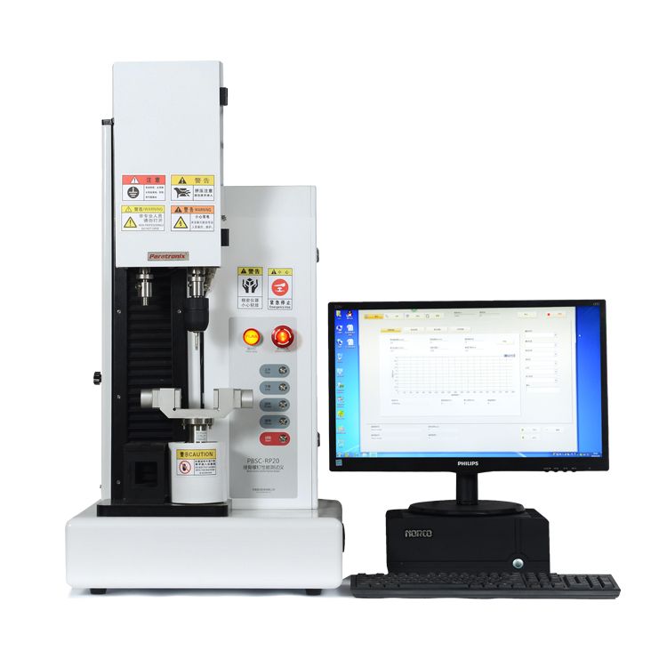
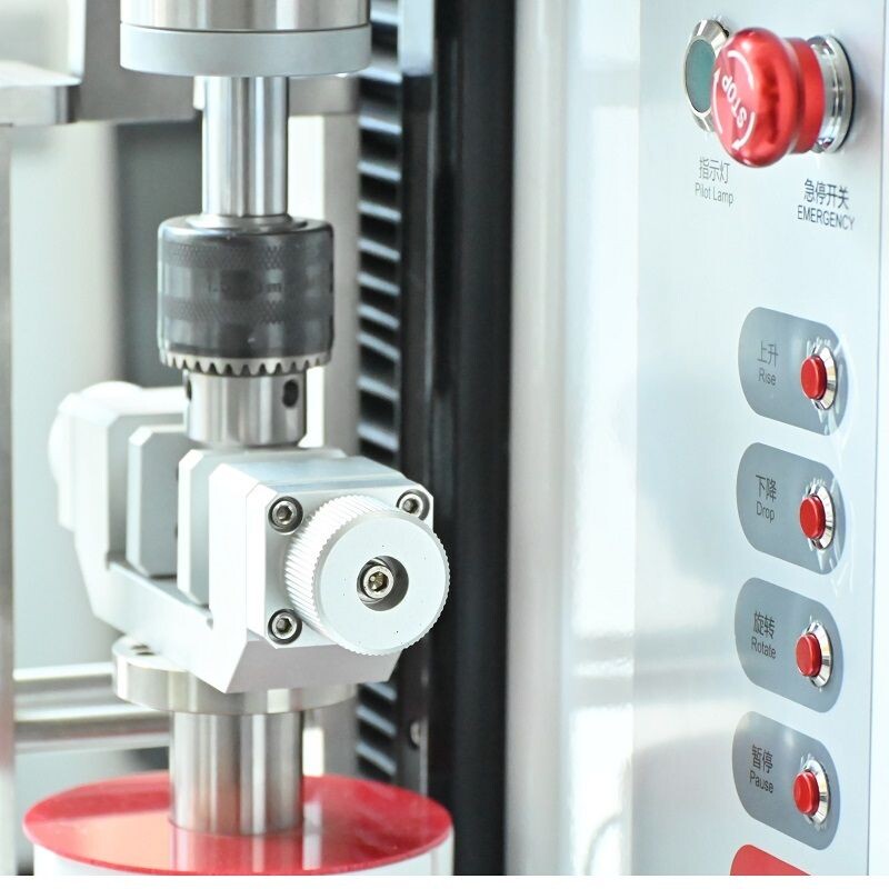
A bone screw driving torque tester measures the rotational force required to advance or remove a surgical screw under controlled conditions. A typical system combines a torque transducer, a drive mechanism, specimen fixtures, and software that records torque against time or angular displacement. Depending on the method and equipment configuration, it may also control rotational speed or axial loading. The resulting curve helps engineers compare screw designs and investigate changes in material, geometry, surface finish, or manufacturing processes.
Driving torque is not the same as torsional strength. Driving tests examine resistance as a screw enters or exits a specified test medium, while torsional strength tests assess behavior under a different loading arrangement, often including failure. Pull-out testing measures resistance to axial extraction rather than rotation. These measurements address different performance questions and should not be treated as interchangeable evidence when evaluating a bone screw or its intended clinical application.
The audience includes orthopedic implant manufacturers, contract testing laboratories, research institutions, and quality teams responsible for design verification or process monitoring. Engineers may use the results to compare thread profiles during development, assess a supplier change, or investigate manufacturing variability. Procurement teams should first define the intended test methods and specimen range, because the required torque capacity, fixtures, control functions, and reporting capabilities depend on those choices.
How The Test Works And What Affects Results
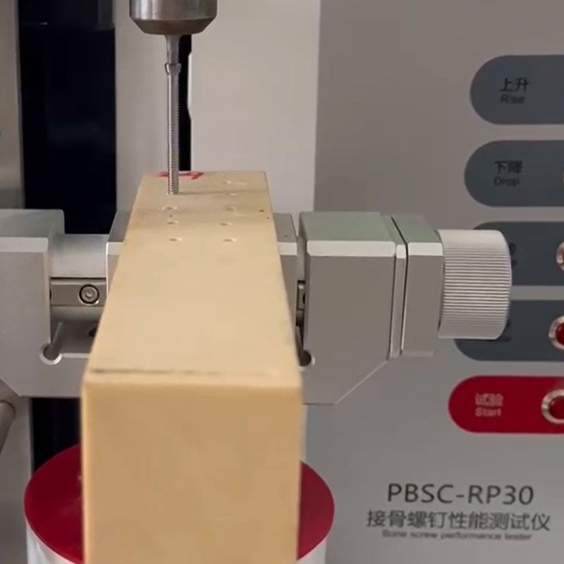
During a typical insertion test, a driver engages the screw head while the specimen is secured in a defined test medium. The system rotates the screw under specified conditions and records torque as the screw advances. A curve can reveal an initial engagement region, increasing resistance, and local peaks associated with cutting or thread formation. The reported value may be a peak or another defined statistic; the protocol must identify precisely how that value is calculated.
Results depend on more than the screw itself. Test block material and condition, pilot-hole dimensions, insertion depth, rotational speed, axial force, driver fit, and alignment can all influence the measurement. Removal torque additionally depends on how the screw was inserted and the interval or conditions before removal. Control these variables across comparison groups, document any deviations, and avoid interpreting a single measured peak as a complete assessment of fixation performance.
A useful test record links the raw curve to the specimen identification, test medium, fixture, driver, instrument settings, and calculation method. Check the torque transducer across the relevant working range and use an appropriate calibration program with traceability to recognized measurement standards. Repeat measurements and a predefined specimen count help characterize variation. Bench data support engineering comparisons, but the relationship to clinical performance depends on the full test design and its limitations.
ASTM F543 And Related Test Methods
ASTM F543 is a standard specification and associated test-method framework for metallic medical bone screws. It addresses several mechanical properties through separate annexes, including driving torque, torsional properties, axial pull-out strength, and self-tapping performance. A laboratory should consult the current applicable edition and the relevant annex before writing its procedure. The standard defines test methods and related requirements; it should not be treated as a universal clinical acceptance limit for every screw design.
For a driving torque study, determine whether the applicable method and specimen conditions match the question being asked. Define the test medium, preparation, screw engagement, insertion conditions, measurements, and reporting rules using the relevant edition. When a project requires a nonstandard material or procedure, document the change and explain its purpose. Results obtained under different protocols should not be presented as directly equivalent without assessing the effect of those differences.
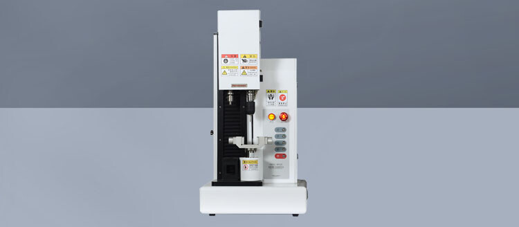
A bone screw driving torque tester may be part of a broader verification program that also considers other applicable standards and regulatory expectations for the target market. Ask the testing laboratory or regulatory team to confirm the relevant editions and acceptance criteria. paratronix supplies testing equipment and lists the PBSC-RP30 Bone Screw Performance Tester as a related product. Request its current specifications and method-specific configuration details before deciding whether it fits an ASTM F543 test plan.
Main Equipment Types And Application Scenarios
Torque measurement setups range from manually operated instruments to motor-driven systems with programmable control and continuous data capture. Manual arrangements can support basic investigative work, but operator-dependent speed, alignment, and data collection require careful management. Motor-driven systems can make it easier to apply and document repeatable motion when properly configured. Neither approach establishes compliance by itself: the complete apparatus, procedure, calibration, and reporting must meet the chosen method.
A dedicated torque system focuses on rotational measurements, while a multipurpose test platform may accommodate additional fixtures or loading modes. A platform intended for insertion, removal, torsion, or pull-out work should be assessed separately for each task: compatible software, load cells, grips, travel, and control capabilities may differ. Confirm whether changing between methods requires additional hardware, recalibration, or operator training, and include those requirements in the purchasing specification.
During development, teams can compare candidate thread geometries using consistent specimens and test blocks. In production support, they may investigate whether a process or material change shifts the torque curve relative to a validated baseline. Independent laboratories can use documented methods to provide comparable reports for customers. These are general use cases, not claims of completed customer projects; the choice of test and interpretation should follow the device manufacturer's risk and verification plans.
How To Select And Qualify A System
Start with the expected torque range for the smallest and largest specimens, including anticipated peak values and reasonable headroom. Ask for accuracy specifications across the actual measurement range rather than relying only on full-scale capacity. Review resolution, sampling rate, rotational speed control, and the way the software identifies peaks. For low-torque specimens, a system with excessive capacity may provide insufficient usable measurement performance; confirm this against the supplier's documented specifications.
Next, review mechanical compatibility. The fixture must secure the selected test medium and maintain alignment without interfering with the screw or driver. Confirm driver interfaces, specimen sizes, insertion depth, available travel, and any axial force or displacement controls required by the protocol. Ask the supplier to identify standard and optional components in the quotation. A demonstration using representative screws and test media can expose fixture or data-capture limitations before purchase.
Before routine use, establish installation checks, calibration status, software access controls where needed, and an operating procedure. Verify settings and calculations with suitable reference checks, then assess repeatability using a representative test setup. Define file retention, export format, traceability, and review responsibilities in line with the laboratory's quality system. Requalify the relevant setup after significant changes to fixtures, software, sensors, or procedures, according to documented risk and change-control practices.
Ownership Costs And Future Trends
The purchase price is only one part of total ownership cost. Include fixtures, drivers, test media, calibration, installation, training, maintenance, software licensing, and replacement components where applicable. Estimate operator time for setup, testing, data review, and report preparation across the expected annual workload. Also consider service availability and downtime. A lower initial quote may be less economical if required accessories or recurring support are excluded from the scope.
To evaluate return on investment, compare a realistic in-house workflow with the cost and turnaround of external testing. Include the cost of establishing and maintaining a qualified method, not just the instrument. Potential benefits may include scheduling control, faster design iterations, and more accessible raw data, but these depend on test volume and staffing. Request an itemized quotation and service terms from paratronix, then compare them with alternatives against the same documented requirements.
Industry development is moving toward more integrated data capture, stronger traceability, and greater automation of repeatable laboratory tasks. These capabilities are valuable only when measurement performance and method control remain sound. As standards, software, and implant designs evolve, periodically review procedures, calibration intervals, fixture condition, and staff competency under the laboratory's quality system. The related article, Self-Tapping Screw Tester Metrics for Torque, Insertion, and Pull-Out Testing, offers a useful next step for comparing complementary measurements.
Search by Keywords