




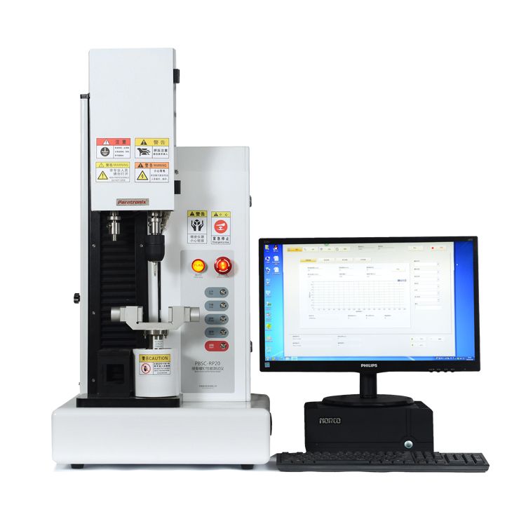
What Is A Bone Screw Insertion Force Tester?
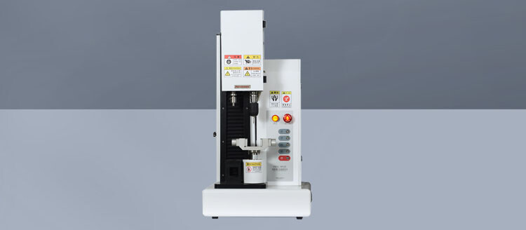
A bone screw insertion force tester is a mechanical test system used to record the axial force and rotational torque associated with driving a screw into a specified test material. The equipment typically combines a linear loading mechanism, a rotating drive, force and torque measurement devices, fixtures, and data acquisition software. Depending on its configuration, it may also support related tests such as screw removal or axial pull-out. The resulting measurements help teams compare screw designs and evaluate performance under controlled laboratory conditions.
Axial force is the load applied along the screw axis, generally reported in newtons. Insertion torque is the resistance to rotation during driving, generally reported in newton metres or newton centimetres. Both signals can change substantially as the screw tip engages, threads form or advance, and the head approaches the surface. A complete force and torque curve can therefore reveal behaviour that a single peak value misses, such as an unstable start or a sudden increase in resistance.
Results are comparative measurements, not direct predictions of clinical outcomes. They depend on the substrate, pilot hole, screw geometry, alignment, drive speed, and the chosen axial loading strategy. Synthetic test blocks can improve consistency between specimens, while biological bone may offer application-specific insights but introduces greater variability. A useful test report identifies these conditions and distinguishes a screening method from a formally validated procedure intended to support a regulatory submission.
How Axial Force And Insertion Torque Are Measured
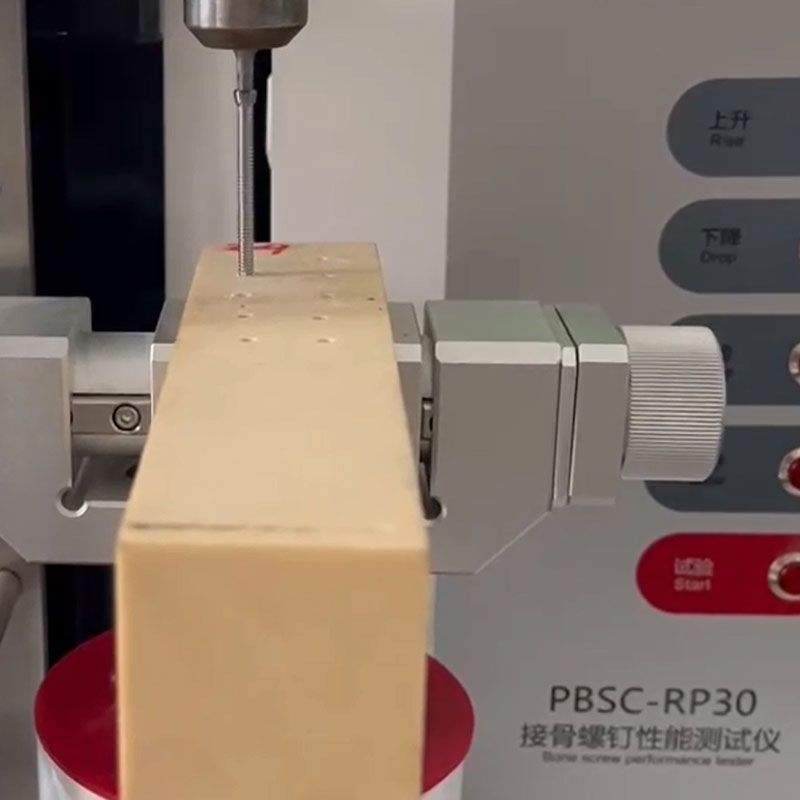
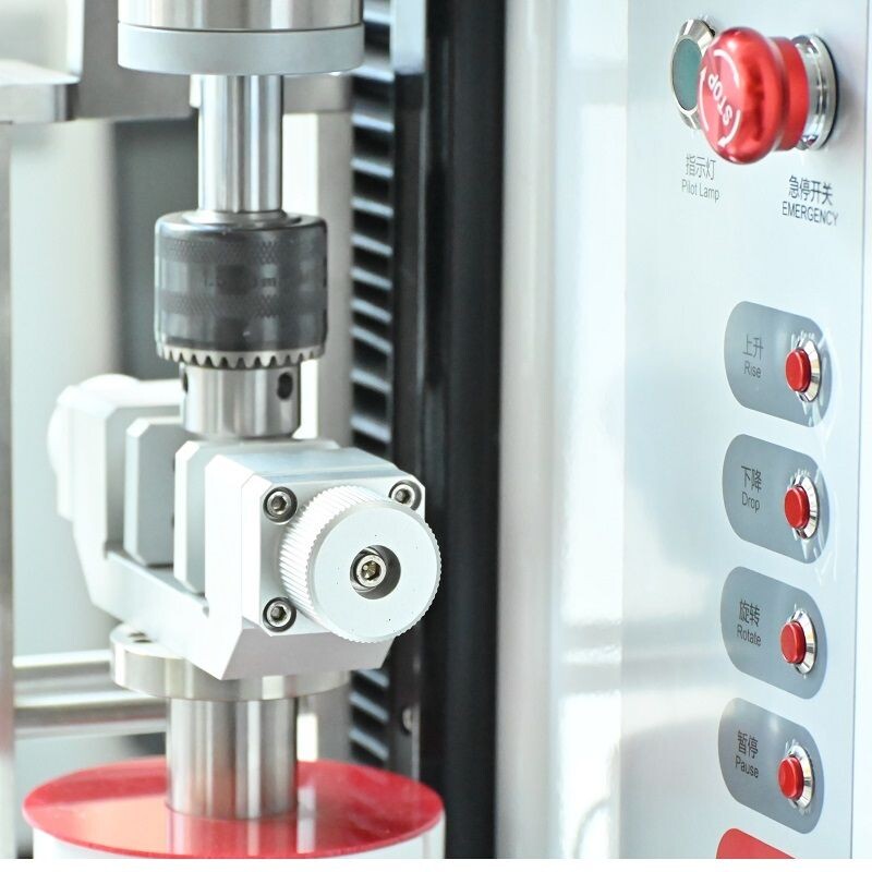
During a test, a drive bit engages the screw while the specimen is held in a fixture that maintains alignment. A torque transducer measures rotational resistance, and a load cell measures the axial force transmitted through the test system. The controller may apply a defined axial force, advance the drive at a specified rate, or use another method appropriate to the procedure. Displacement, angular position, time, and rotation speed provide context for interpreting the force and torque signals.
Force control and displacement control are not interchangeable. Under force control, the system adjusts motion to maintain a target axial load; under displacement control, it follows a prescribed movement while force varies. The selected approach can influence thread engagement and the measured torque. Before comparing results, verify that the control mode, setpoints, sampling rate, filtering, and data processing are equivalent. A synchronized record is particularly useful when investigating whether a torque change coincides with a change in axial loading.
Typical outputs include maximum insertion torque, torque at a defined depth, axial force at initial engagement, and the shape of the force and torque curves. The appropriate endpoint should be established before testing rather than selected after inspecting results. Confirm sensor calibration and usable measurement range, including the uncertainty relevant to the expected loads. Fixtures, bit fit, backlash, and machine compliance can also influence readings, so method development should include alignment checks and repeatability studies.
Equipment Types And Selection Criteria
Equipment ranges from torque-focused systems with separately applied axial loading to integrated systems that control and record both rotation and linear motion. A multipurpose mechanical tester may accommodate insertion and pull-out fixtures, while a dedicated bone screw platform can simplify a recurring workflow. The best configuration depends on the method and specimen, not the equipment label. Ask which motions can operate simultaneously, how the axial load is applied, and whether all required channels are captured on the same time base.
Select force and torque capacities around the expected working values, including foreseeable peaks and a suitable margin against overload. A high-capacity sensor may be unsuitable for small measurements if its accuracy or resolution is inadequate at the low end. Request the usable range and uncertainty information for the actual sensor and calibration arrangement. Also check available travel, rotational speed, specimen clearance, fixture compatibility, and whether the system can accommodate different screw lengths and drive interfaces.
Software and service requirements deserve equal attention. Confirm that operators can define test stages, set stop conditions, display synchronized curves, export raw data, and document method revisions. For regulated work, assess access controls, audit trail capabilities, and data integrity against your own procedures; do not assume they are included. Ask about calibration intervals, spare parts, technical support, installation requirements, and training. A demonstration using representative screws and substrates can expose practical limitations before purchase.
Applications And Relevant Standards
Orthopaedic implant manufacturers use insertion testing during design comparison, process development, and quality investigations. Contract laboratories may run repeatable methods for several clients, while research groups study the effects of thread geometry, pilot-hole preparation, and substrate properties. Teams working on dental or other fixation screws may also benefit from the measurement principles, provided their fixtures and procedures match the intended device. In every application, acceptance criteria should come from the device specification and validation plan rather than from the tester alone.
ASTM F543 addresses metallic medical bone screws and includes test methods relevant to mechanical properties, including insertion and removal torque and axial pull-out. ASTM F1839 covers rigid polyurethane foam for use as a standard material for testing orthopaedic devices. Applicability depends on the device, test objective, and current edition, and using a named standard does not automatically establish compliance. Review the complete applicable documents, identify required apparatus and specimen conditions, and document any justified deviations.
For a procurement review, paratronix offers the PBSC-RP30 Bone Screw Performance Tester as a related product to discuss alongside the intended insertion and pull-out methods. Its broader testing-equipment portfolio includes torque and multipurpose testers, as well as medical packaging test equipment. Request the current product specifications, supported fixtures, measurement ranges, and a method-specific quotation directly from the supplier. Confirm any claimed standard coverage against the proposed configuration and your laboratory's requirements before placing an order.
Test Workflow And Quality Control
Begin by defining the research question, test endpoint, specimen count, and acceptance or comparison criteria. Record screw dimensions, material and lot, as well as substrate type, density or grade, conditioning, and specimen preparation. Specify whether a pilot hole is used and document its diameter, depth, and preparation method. Mount the substrate securely, align the screw and driver with the loading axis, and select a drive bit that fits the screw head without excessive play.
Before running specimens, verify sensor status, zero readings as appropriate, and check the fixture and travel limits. Program the axial loading mode, rotation speed, insertion depth or other endpoint, and safety stops. Run a trial to confirm engagement and data capture, then test the planned specimens under the same documented conditions. Do not reuse a damaged test location unless the protocol specifically calls for it. Record interruptions, unusual driver slip, substrate cracking, and other observations that may affect interpretation.
Review the complete curves as well as summary values, and retain raw data with the method version, equipment identifiers, calibration status, and operator records. Investigate outliers using predefined rules rather than removing inconvenient results. Periodic checks should cover transducer calibration, alignment, fixture wear, drive-bit condition, and software or configuration changes. Reassess repeatability after maintenance, a new substrate lot, or a significant method change. For guidance on related measurements, consult the articles on self-tapping screw test metrics and selecting an appropriate load range.
Ownership Costs And Future Trends
The purchase price is only one part of the total cost of ownership. Include force and torque sensors, calibration, fixtures, compatible drivers, installation, training, software options, maintenance, and replacement parts. Consumables such as test blocks and screws, along with operator time and laboratory space, also affect the cost per test. Compare quotations on the same scope, including data export and service coverage, and establish which items are optional or require recurring fees.
Estimate return on investment by comparing expected testing volume and costs with the current approach, including outsourced fees, shipping, turnaround time, and internal labour. Consider the value of faster design iterations and improved traceability, but treat these benefits as assumptions until supported by local data. An in-house system may not be economical for infrequent testing or methods requiring specialized expertise. A contract laboratory or a shared multipurpose platform can be a practical alternative for lower volumes.
Future development is likely to emphasize synchronized multichannel data, more consistent control of loading, and easier integration with laboratory records. Automated analysis may help reviewers identify curve features, but algorithms still require validation and human oversight. As devices and test materials evolve, laboratories should periodically review methods, applicable standard editions, and equipment capacity. When evaluating a bone screw insertion force tester, provide suppliers with representative specimens, expected load ranges, and reporting requirements so that the proposed configuration can be assessed against a specific workflow.
 Self-Tapping Screw Tester Metrics for Torque, Insertion, and Pull-Out TestingSelf Tapping Screw Tester metrics for insertion torque, stripping torque, seating, and pull-out force. Learn how to achieve reliable fastening tests and stronger quality control.
 How to choose the right load range for a bone screw insertion force testerBone screw insertion force tester guide: choose the right load range for accurate force data, reliable resolution, and confident screw testing results.
Search by Keywords