




Recent Posts
 How to choose the right load range for a bone screw insertion force testerSep 23, 2026
 How to select torque range for a bone screw torsion testerSep 22, 2026
 What does a bone screw torsion tester measure during implant testing?Sep 22, 2026
 When ASTM F1306 is suitable for laminated film puncture testingSep 21, 2026
 Selecting a laminated film puncture force tester for low-force filmsSep 21, 2026
Start with the Expected Peak, Then Preserve Useful Resolution
Select the load range from the highest force that the test is expected to generate, not from the nominal size of the bone screw or the apparent strength of the sample. The selected capacity must remain above every credible peak during insertion, including transient spikes caused by thread engagement, cortical breakthrough, seating, misalignment, or a dense material region. At the same time, the range should not be so high that meaningful changes in axial force disappear within the instrument's resolution, noise level, or low-load accuracy band.
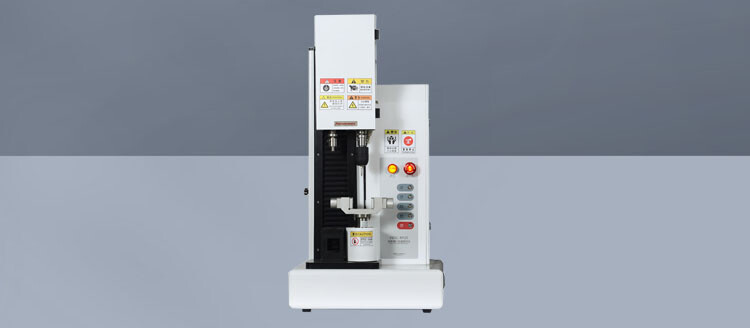
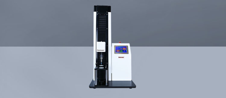
For a bone screw insertion force tester, the practical target is a range that places normal test peaks in the central working portion of the load cell rather than close to zero or close to full capacity. This leaves room for short-duration excursions while retaining enough sensitivity to distinguish differences caused by screw geometry, pilot-hole condition, substrate density, coating, or insertion speed.
Load range selection should be treated as a measurement-chain decision. The screw, the driver, the fixture, the simulated bone material, the motion path, and the data-acquisition settings all influence the force signal. A load cell selected without reference to those conditions can produce a technically valid reading that is still poorly suited to comparison work.
Separate Axial Force from Insertion Torque
A frequent source of range-selection error is treating torque and axial force as interchangeable. They are related during screw placement, but they describe different mechanical actions. Insertion torque reflects rotational resistance at the thread interface. Axial force reflects the compressive force applied along the screw axis, often needed to maintain engagement between the driver and screw head and to advance the thread into the material.
A test arrangement may record torque, axial force, or both. If the stated evaluation objective is insertion torque, a torque transducer requires its own capacity selection. The axial load cell should still be selected according to the force actually transmitted through the fixture, not according to the torque range. A high-torque event does not automatically imply a high axial-force event. Conversely, substantial downward force can occur with moderate torque when the screw is being held against a surface, when the driver is pressed to prevent cam-out, or when the fixture introduces friction.
Before choosing capacity, define the output that will be used to compare specimens. Typical force-related outputs include peak axial force, mean force during thread engagement, force at initial penetration, force near final seating, and the force-time trace. Each output places different demands on resolution. A system used to detect a small shift in mean insertion force needs a more sensitive load cell than one used only to confirm that a force ceiling was not exceeded.
Build a Credible Peak-Force Envelope
Past test records are the strongest basis for selecting a range, provided the historical setup matches the proposed one. Compare screw diameter, thread form, screw length, tip design, material, surface finish, driver interface, rotational speed, insertion depth, pilot-hole preparation, and substrate construction. Changing one of these variables can alter the peak force enough to make an earlier range unsuitable.
When prior data are unavailable, run a limited exploratory series with a conservatively high-capacity sensor. The purpose is not to establish final performance results. It is to observe the force profile and identify events that determine capacity: start-up contact, cutting or self-tapping action, transition between material layers, head seating, and the effect of a deliberately imperfect alignment. Review the full trace rather than relying only on a displayed maximum. A sharp peak may be real, but it may also arise from fixture impact, backlash take-up, or a control-loop disturbance.
The peak-force envelope should include conditions that are intended to be part of the method and credible deviations that can occur during normal execution. Consider:
- the densest or hardest substrate variant expected in the test program, including layered constructs with a dense outer region;
- the smallest pilot hole, no-pilot-hole condition, or other preparation state that increases thread-cutting resistance;
- the screw configuration most likely to require high seating force, rather than only the most commonly tested configuration;
- maximum intended insertion speed, because dynamic effects and control response can raise short peaks even where steady insertion force changes little;
- driver engagement conditions, especially recessed heads or interfaces that require additional axial preload to avoid slippage;
- fixture stops, seating surfaces, and travel limits that could create contact loads unrelated to the screw-substrate interaction.
Do not convert a single exploratory maximum directly into the final load-cell rating. A capacity margin is required for specimen variation, setup tolerance, and short transient events. The appropriate margin depends on the repeatability of the setup and the severity of plausible peaks. A highly controlled fixture with stable material may need less reserve than a test method spanning several screw designs and substrate grades. The important point is to document why the selected upper limit is above the anticipated force, rather than choosing an arbitrary large range.
Why an Oversized Range Can Distort the Evaluation
Capacity alone does not define measurement quality. Load cells have characteristics such as resolution, repeatability, nonlinearity, hysteresis, zero stability, and calibration uncertainty. Their usable behavior near the bottom of the scale may differ from behavior in the middle of the range. When routine insertion forces occupy only a small fraction of a very large load range, small but relevant changes may be buried by signal noise, digitization limits, fixture vibration, or zero drift.
This problem is especially visible when comparing similar screw designs. A trace can look smooth and repeatable at broad scale while masking differences in initial engagement force or seating behavior. The result may be an incorrect conclusion that two designs behave alike, when the instrument simply lacks enough effective sensitivity in the region where their differences occur.
Oversizing also complicates troubleshooting. If the force signal changes by only a few display increments between specimens, it becomes difficult to determine whether the change comes from the screw, the material block, the driver path, or the measurement system. A tighter but adequately protected range makes the test trace more diagnostic.
For this reason, a broad-range sensor is useful during method development, screening, or unknown-condition trials, but it is not automatically the best sensor for comparative testing. Where the test program covers widely different screw families, interchangeable load cells or separate validated setups can be more defensible than forcing all conditions into one high-capacity range.
Read the Force Trace Before Finalizing the Sensor
A single peak value hides the mechanical sequence. Examine the time history or displacement-linked force curve during preliminary runs. The shape of the trace often reveals whether the selected range is appropriate and whether the method itself needs adjustment.
Transient peaks require particular care. A peak created when the crosshead contacts a stop should not be treated as insertion force. Conversely, removing every short peak through aggressive filtering can erase a genuine event at thread start or cortical penetration. Data filtering, sampling rate, and mechanical motion must be reviewed together. The selected load range should accommodate real events, while the method should exclude fixture artifacts through proper travel control and fixture design rather than post-processing alone.
Account for the Complete Mechanical Load Path
The load cell does not measure an abstract force value; it measures the load transmitted through its mounting path. If the screw is inserted at an angle, lateral components can introduce bending. A sensor intended for axial compression may give unstable results or suffer damage when side loading is present. The correct answer is often to improve alignment, add appropriate guidance, or use a fixture that isolates the intended axial component, rather than simply selecting a larger axial load cell.
Fixture mass and moving components also matter in motorized systems. Rapid acceleration or reversal can create inertial loads that appear in the recorded signal. Those loads may be small compared with a high-capacity range but significant when a lower range is selected for sensitivity. Run the motion profile without a specimen to characterize baseline force. If the unloaded trace contains substantial peaks, correct the motion sequence, cable routing, mechanical friction, or fixture interference before setting the final range.
Driver preload needs a clear definition. Some insertion methods intentionally apply a controlled axial preload throughout rotation. Others permit the screw to advance with minimal imposed force. These methods should not share a load-range assumption. A controlled preload can dominate the force channel even though the screw-thread interaction is changing underneath it. In that situation, select enough range for the commanded preload plus the expected insertion-related variation, and ensure the sensor resolution is sufficient to detect that variation.
Material and Preparation Conditions Change the Answer
Bone analogs, cadaveric material, and engineered test blocks do not create the same force behavior. Density gradients, anisotropy, moisture condition, layer thickness, and temperature can alter both average force and peak events. Even within a synthetic material family, differences in foam density or outer-shell construction can move the normal operating window. The selected range should be based on the material condition specified by the test method, not on an informal assumption that all bone substitutes behave similarly.
Pilot-hole diameter and depth deserve the same attention as the screw itself. A small change in pilot-hole preparation can shift a test from a thread-forming condition to a thread-following condition. Tapping, drilling, irrigation, debris removal, and hole alignment may also change insertion behavior. If those controls are not fixed, the resulting spread can be wrongly attributed to screw design and may prompt an unnecessarily large sensor selection.
Final seating is another distinct phase. The axial force applied while threads advance through the substrate can differ substantially from the force needed to seat a head against a plate, washer, or simulated cortical surface. If seating force is part of the evaluation, include the actual mating component and its surface condition in preliminary range studies. Testing a screw in an open block and then extrapolating capacity to a plate-and-screw assembly can miss the highest-force portion of the sequence.
Match Capacity to the Intended Comparison
For screening across very different screw sizes or substrate conditions, the selected range should cover the broadest valid envelope, with enough resolution to separate the minimum meaningful difference. For development work on a single screw family, a narrower range is often justified because the expected force band is better defined. The range selected for incoming verification may differ again from the range used for design characterization, since the pass/fail threshold and required evidence are not necessarily the same.
Where both low-force and high-force conditions are essential, avoid treating one range as universally correct. Establish separate force bands and document which sensor applies to each condition. The test report should identify load-cell capacity, calibration status, measurement direction, sampling settings, preload control, fixture configuration, and the force metric reported. Without these details, force values from separate evaluations can appear comparable while representing different mechanical conditions.
Confirm the Choice During Method Qualification
After selecting the provisional range, repeat representative insertions across the intended condition set. Review whether normal peaks remain comfortably below capacity and whether low-force regions show stable, interpretable data. Check zero before and after a run, especially after high-load events. A persistent zero shift, unexpected hysteresis, or trace change after a near-capacity event indicates that the chosen range or mechanical setup requires further review.
The final specification should state more than a nominal maximum load. It should define the preferred operating window, the overload response, the required resolution for the reported metric, acceptable zero drift, calibration interval, and any restriction on off-axis loading. This turns load range from a catalog selection into a controlled part of the test method.
A well-chosen range captures genuine insertion-force variation without sacrificing headroom for valid peaks. That balance produces data that are easier to compare, investigate, and defend when screw design, material condition, or insertion procedure changes.
Leave A Reply
Search by Keywords