




Recent Posts
 How to select torque range for a bone screw torsion testerSep 22, 2026
 What does a bone screw torsion tester measure during implant testing?Sep 22, 2026
 When ASTM F1306 is suitable for laminated film puncture testingSep 21, 2026
 Selecting a laminated film puncture force tester for low-force filmsSep 21, 2026
 Which standards should an ampoule break force tester support?Sep 20, 2026
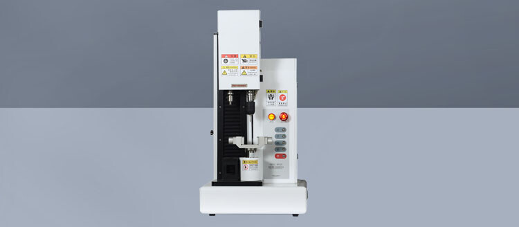
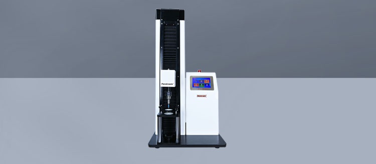

Selecting a torque range for a Bone Screw Torsion Tester is not simply a matter of choosing the largest available sensor. For technical evaluators, the real objective is more demanding: obtain reliable torsional data around the point that matters—elastic deformation, yielding, maximum torque, or fracture—while retaining enough resolution to distinguish meaningful differences between screw designs, manufacturing lots, and materials.
A tester that is oversized may safely withstand every specimen failure but produce measurements that are too coarse for development or quality comparison. A tester with an insufficient range, on the other hand, may overload its torque transducer before the screw reaches failure. The right choice sits between those two risks. It should reflect the expected torsional performance of the complete bone screw, the intended test method, and the level of decision-making confidence required by the laboratory.
This guide outlines a practical selection process for laboratories evaluating a Bone Screw Torsion Tester for orthopedic implant development, verification testing, supplier qualification, or routine quality assessment.
Begin with the torque that the screw is expected to withstand
The starting point is not the tester catalogue. It is the expected torsional behavior of the screw. Review available engineering data, previous test reports, design validation records, material specifications, and similar products already in production. The key value is the anticipated maximum torque before fracture or another defined failure event.
For bone screws, torsional capacity can vary substantially with nominal diameter, core diameter, thread geometry, material grade, heat treatment, cannulation, and manufacturing features such as self-tapping flutes. A small cannulated screw may fail at a torque level far below that of a larger solid cortical screw, even when both are made from the same alloy. It is therefore risky to select one torque range based only on the word “bone screw.”
When historical data are limited, use conservative engineering estimates and plan a short feasibility study. Testing a representative sample on a broader-range system can help establish a realistic failure-torque window before the final transducer range is specified.
Identify which torque value actually drives the decision
Technical teams sometimes use “maximum torque” to describe several different measurements. Before selecting equipment, define the result needed for each test program:
- Yield torque: the torque associated with the onset of permanent deformation or a specified offset criterion.
- Maximum torque: the highest torque reached during the test.
- Fracture torque: the torque at the moment the screw breaks.
- Torsional stiffness: the relationship between applied torque and angle of rotation in the elastic region.
- Drive torque or insertion-related torque: a different application that may require separate fixtures and test conditions.
A laboratory focused on fracture torque can tolerate a different measurement strategy from one studying subtle shifts in torsional stiffness. If the goal is to compare design iterations with only modest differences in performance, sensor sensitivity becomes just as important as ultimate capacity.
Use the working portion of the torque range—not its headline capacity
Every torque transducer has a rated capacity, but the full scale number alone does not describe how useful it will be for a specific screw. In practice, the expected peak torque should fall comfortably within the calibrated working range of the system. A commonly used selection principle is to place typical maximum test torque in the middle-to-upper portion of the sensor range, rather than near the bottom or at the limit.
As a general engineering guideline, expected failure torque is often best positioned at approximately 20% to 80% of full-scale capacity. Many laboratories prefer a narrower operational zone—often around 30% to 70% of full scale—when repeatability and discrimination between samples are especially important. The exact target depends on the transducer’s stated accuracy, resolution, linearity, and overload characteristics.
For example, if a screw family is expected to fracture around a certain moderate torque level, selecting a transducer rated only slightly above that value may appear efficient but leaves little room for lot-to-lot variation or unexpected high-strength specimens. Selecting a sensor ten times larger may be equally problematic if the required yield or stiffness calculation depends on fine changes early in the torque-angle curve.
Resolution matters most before the screw breaks
A dramatic fracture event is easy to see. The difficult part is often the data leading up to it. During product development and comparative testing, evaluators may need to identify the initial linear region, the yield point, a torque drop associated with thread damage, or a gradual change in torsional stiffness. These details are shaped by the tester’s torque resolution, data acquisition behavior, and mechanical stability.
Ask the supplier to clarify the difference between display resolution and meaningful measurement performance. A display may show many decimal places, but that does not automatically mean the complete system can repeat measurements at that level. Consider the stated accuracy of the torque transducer, repeatability, sampling rate, noise characteristics, calibration traceability, and the influence of the fixture.
For a Bone Screw Torsion Tester, the measured signal should be stable when no load is applied and should rise smoothly during controlled rotation. If the baseline drifts, the gripping arrangement slips, or the system introduces vibration, a high-resolution transducer will not solve the problem on its own.
Do not select range without considering the applicable test method
Many orthopedic screw torsion programs refer to ASTM F543 or relevant ISO requirements, customer protocols, internal procedures, or regulatory submission methods. These documents may define or influence specimen preparation, clamping length, rotational speed, torque-angle recording, failure criteria, and reporting requirements. The test method affects range selection because it determines what needs to be measured and how the sample is loaded.
For instance, a method that requires calculation of torsional yield strength and stiffness places greater emphasis on clean angle measurement and data quality in the early and middle stages of loading. A method focused primarily on breakage torque still requires adequate resolution, but its most important requirement may be sufficient capacity and safe capture of the peak event.
Technical evaluators should review the standard version specified by their quality system or customer contract rather than assuming that any torsion machine is automatically configured for bone screw testing. Standards can require specific specimen support arrangements and test conditions. The equipment should support the method, not force the method to adapt to a generic fixture.
The screw’s geometry can change the equipment specification
Torque capacity is only one part of selection. A tester must also hold the screw in a way that transmits rotation without introducing unintended bending, crushing, slippage, or stress concentration. This is especially important for small orthopedic screws, screws with unusual drive recesses, and cannulated designs.
Evaluate the product family in practical terms:
- Nominal screw diameter and minimum core diameter
- Overall length and required exposed test length
- Solid versus cannulated construction
- Head style and drive interface
- Thread profile, flute geometry, and self-tapping features
- Material type, including titanium alloys, stainless steel, or other implant materials
- Whether the test requires gripping the head, shank, thread, or a dedicated test adaptor
A torsion result is only credible when the specimen fails as intended rather than at a damaged grip location. For this reason, fixture design should be reviewed alongside transducer range. The best torque sensor cannot compensate for a clamp that distorts the screw or permits micro-slip under load.
Alignment deserves more attention than it usually receives
Ideally, the screw axis should coincide with the rotational axis of the tester. Misalignment can introduce bending and axial loads into what should be a predominantly torsional test. The resulting curve may look irregular, and fracture may occur at a location that does not represent the screw’s genuine torsional capability.
Look for a test setup that allows careful alignment, repeatable gauge length adjustment, and secure specimen positioning. If several screw sizes are tested, modular fixtures or dedicated adaptors may be more appropriate than one universal clamp used beyond its comfortable range.
Choose a range strategy for the full product portfolio
One-range systems are convenient when a laboratory evaluates a narrow, stable screw family. They become less attractive when the same team must test tiny trauma screws, larger orthopedic fixation screws, prototype designs, and incoming components from different suppliers.
In such cases, an interchangeable torque sensor strategy can make more technical sense than choosing one oversized range. A lower-range sensor may be used for smaller screws and detailed development work, while a higher-range sensor can accommodate larger or stronger products without creating overload concerns. This approach also supports more defensible comparisons because each product is measured within an appropriate portion of the sensor’s operating range.
There is a practical balance to consider. Multiple ranges add equipment complexity, calibration management, and operator setup requirements. The value is strongest when the torque spread across the portfolio is wide enough that a single transducer would force some samples too close to the bottom of the scale and others too close to the top.
Check angular measurement, rotation control, and data capture
Torsion testing is a torque-and-angle exercise. A torque range may be perfectly selected while the test still fails to deliver useful engineering insight because angular data are incomplete or poorly controlled.
Confirm that the system can measure and record angular displacement with suitable resolution for the selected method. Controlled rotation speed is also important. Changing rotation rate can influence observed behavior, especially when comparing results across laboratories or validating a documented test procedure. The tester should provide stable, repeatable speed control and capture torque-angle data at a sampling rate capable of recording the peak and the post-yield response.
For routine quality work, software should make it straightforward to retain raw curves as well as calculated results. A single maximum-torque number can be useful, but the torque-angle trace often explains whether a result came from normal material behavior, grip slippage, premature damage, or a setup error.
Build an overload margin into the purchase decision
Unexpected results are not rare in orthopedic testing. A revised heat treatment, a material lot at the high end of specification, a design change, or even a sample that does not fracture where expected can push torque beyond predicted values. Selecting a transducer with no margin may create avoidable downtime and risk to the instrument.
Review both the rated capacity and the manufacturer’s permitted overload limit. These are not the same thing. An overload rating may describe short-duration survival rather than a condition suitable for normal testing or guaranteed measurement accuracy. The preferred approach is to select a range that avoids overload during credible worst-case testing, rather than relying on overload protection as part of routine operation.
A practical evaluation checklist for a Bone Screw Torsion Tester
Before finalizing a specification, technical evaluators should be able to answer the following questions clearly:
- What are the expected minimum, typical, and maximum failure torque values across all target screws?
- Which output is critical: yield torque, peak torque, fracture torque, stiffness, or a combination?
- Will typical peak torque occupy a useful part of the selected transducer range?
- Does the required test method define speed, gauge length, gripping conditions, or reporting calculations?
- Can the fixtures securely accommodate the smallest, largest, solid, and cannulated specimens?
- Is torque-axis alignment repeatable between operators and test batches?
- Are torque accuracy, angular measurement, data rate, and calibration documentation suitable for the intended use?
- Will future product sizes or design changes require a second torque range?
A supplier discussion is more productive when these answers are available. Rather than asking only, “What torque range do you recommend?”, provide screw drawings, expected performance data, sample quantities, applicable standards, and the intended reporting outputs. This gives the equipment provider enough context to assess the complete test configuration.
Make the final choice around measurement confidence
The most appropriate torque range is the one that captures the true behavior of the bone screw with enough sensitivity to support a technical decision and enough capacity to protect the system under realistic variation. Bigger is not automatically safer from a measurement perspective, and smaller is not automatically more precise in real-world use.
For laboratories building or updating a bone screw torsion test capability, the strongest selection process combines estimated failure torque, standard requirements, fixture design, angle measurement, and future product needs. Paratronix Instruments applies the same measurement-focused approach used across specialized test equipment projects: define the specimen, define the performance question, and configure the test system around reliable, repeatable evidence. When torque range is selected this way, the resulting data is far more useful than a simple pass-or-fail number—it becomes a dependable basis for engineering and quality decisions.
Leave A Reply
Search by Keywords