




Recent Posts
 Can an ISO 15105-2 oxygen tester measure high-barrier films?Nov 06, 2026
 How to check an oxygen tester against ISO 15105-2 requirementsNov 06, 2026
 How to prepare film samples for ISO 15105-2 oxygen testingNov 06, 2026
 Choosing an ISO 15105-2 oxygen tester by measurement rangeNov 06, 2026
 How does an ISO 15105-2 oxygen permeability tester work?Nov 06, 2026
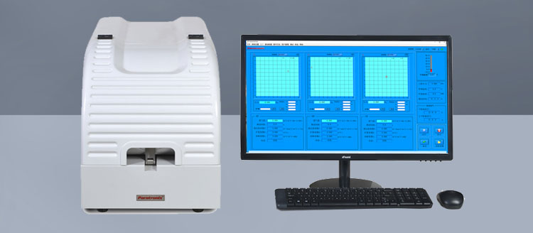
An oxygen tester is not demonstrably suitable for ISO 15105-2 testing simply because its specification lists the standard. The decisive question is whether the complete measurement system—test cell, pressure control, oxygen detection, environmental conditioning, calibration and calculation—can perform the applicable equal-pressure method on the intended material at the required test conditions.
Begin with the edition of ISO 15105-2 specified by the test request or quality agreement. Compare that document with the instrument’s operating instructions and supporting evidence, not just its sales literature. A tester can measure oxygen transmission and still have limitations that prevent a particular sample, humidity condition or reporting requirement from being assessed as intended.
Establish what the standard claim covers
ISO 15105-2 addresses the determination of gas transmission rate through plastics film and sheeting by an equal-pressure method. It is not a universal certification for every oxygen permeability instrument, nor does it automatically establish a method for testing complete packages. Confirm that the material, specimen form and test objective fall within the scope of the applicable edition and any customer-specific method.
Ask the equipment supplier to identify the edition referenced in its claim and provide a clause-by-clause explanation of how the instrument and its prescribed operating procedure address the relevant requirements. That explanation should distinguish between capabilities supplied as standard, optional accessories, operator-controlled procedures and requirements that depend on the laboratory.
For example, a system may be capable of controlling chamber temperature but require an additional conditioning unit to establish a specified humidity. In that case, the base instrument’s standard claim does not establish that the complete test can be performed under the requested conditions. The configuration being evaluated must be the configuration used for testing.
Also distinguish an instrument capability statement from an accredited test result. ISO 15105-2 is a test method; its presence on a specification sheet is not, by itself, an ISO certification of the equipment or proof that a laboratory is accredited to perform the test. Where accreditation is required, check the laboratory’s current scope for the method, material or product category, conditions and measurement range relevant to the work.
Verify the equal-pressure measurement principle
In an equal-pressure arrangement, a specimen separates a gas-rich side from a carrier-gas side. The total pressures on the two sides are maintained approximately equal, while a difference in the partial pressure of the test gas drives permeation through the material. The gas passing through the specimen is carried to a detector, from which the transmission rate is determined.
This distinction matters because equal total pressure does not mean zero driving force. Oxygen can move through the specimen even when there is little pressure difference across it, provided that the oxygen partial pressures differ. Conversely, an instrument that relies on a substantial total-pressure difference across the film uses a different measurement approach and should not be treated as equivalent solely because it produces an oxygen transmission value.
Examine the flow path and ask how the system establishes and maintains the required pressure relationship during purging, measurement and any automatic valve switching. A transient pressure imbalance can stress a thin specimen, disturb the sealed area or introduce leakage. For sensitive films, the supplier should be able to explain how pressure is controlled and how the operator checks that the cell is functioning as intended.
The detector is another part of the method, not an interchangeable detail. Ask what quantity it measures, how its signal is converted to oxygen transmission rate, and what gas composition and flow conditions are required. Different detection technologies have different sensitivities to carrier gas, moisture, contaminants and drift. Their suitability must be demonstrated for the intended range and conditions rather than assumed from the sensor name.
Match the measurement range to the material
A stated measurement range is useful only when its basis is clear. Check the units, exposed test area, test conditions and whether the limits refer to the detector signal, instrument configuration or calculated transmission rate. A range quoted for one cell area or set of conditions may not translate directly to another.
For high-barrier materials, the lower end of the range deserves particular scrutiny. The measured oxygen signal must be distinguishable from system background, residual oxygen, leakage and detector noise. Request evidence of the blank response, detection or quantification capability and repeatability under conditions relevant to the intended material. A numerical lower limit without the associated conditions and evaluation method gives little basis for comparison.
At the high-transmission end, assess whether the detector, carrier-gas flow and calculation remain valid without saturation or excessive oxygen concentration on the carrier side. Confirm whether the instrument automatically changes ranges or flow settings and whether such changes affect the applicable procedure.
The practical test duration is also material-dependent. A low detector limit does not guarantee a short test: oxygen must move through the specimen and the apparatus response must stabilize sufficiently for a valid result. Thick specimens, multilayer structures and materials that absorb or release gas can take longer to approach the required measurement condition. Ask how the software identifies a stable result and whether its automatic endpoint can be reviewed or overridden under a documented procedure.
Check the specimen, cell and sealing arrangement
The test cell must expose a known area of intact material while preventing oxygen from bypassing the specimen. Review the cell drawings or specifications for the exposed area, clamping arrangement, sealing materials and allowable specimen dimensions. The area used in the calculation should correspond to the actual opening and seal geometry, not merely the nominal size of the cut sample.
Confirm that the specimen can be mounted without wrinkles, punctures, excessive compression or edge leakage. Very thin films, stiff sheets, coated materials and laminated structures can present different sealing problems. A seal that works well on a smooth film is not necessarily adequate on a textured or uneven surface. Ask what leak-check procedure is prescribed and what evidence is available for the proposed sample type.
For asymmetric laminates, document which surface faces the oxygen-rich side and which faces the carrier side. Layer sequence can affect conditioning and transient behaviour, so orientation must be consistent when comparing results. Where the applicable method or test plan specifies preparation, conditioning or replicate specimens, verify that the instrument’s cell size and sample-handling procedure allow those requirements to be met.
Do not assume that a flat-film cell validates a complete package test. Testing bottles, trays or other finished articles can require different fixtures and procedures, with different potential leakage paths and exposed-area definitions. Any package-testing claim should be assessed against the method specified for that product and the actual fixture supplied.
Review temperature, humidity and gas control as a complete system
Oxygen transmission depends on test conditions as well as the material. Temperature affects permeation, and moisture can substantially alter the barrier behaviour of moisture-sensitive layers. Results should therefore be compared only when the specified conditions, conditioning history and measurement basis are understood.
Check the permitted temperature range, set-point resolution, stability and the location of the temperature sensor. A chamber set point is not necessarily the specimen temperature. Evidence from a temperature verification at or near the test position is more informative than a controller display alone, especially if the cell, gas lines and surrounding enclosure are controlled separately.
For humidity-controlled work, establish whether relative humidity can be controlled on the oxygen side, carrier side or both. A single humidity specification does not establish that an asymmetric condition can be produced. Check the required gas flows, humidification arrangements, measurement locations and how condensation is prevented. If humidity is generated outside the cell, the gas arriving at the specimen may not have the same condition as the humidifier outlet unless the line temperature and arrangement are appropriate.
Gas quality and flow measurement also matter. Residual oxygen in the carrier gas contributes to background; contamination or unstable flow can affect detector response. Review the prescribed gas purity, filtration, pressure and flow requirements, then verify that the site can supply them. Ask how flow is measured or controlled and how the relevant devices are calibrated or verified.
Separate calibration from a check of the whole test
A detector calibration addresses only part of the measurement chain. Depending on the system, valid results also depend on flow, exposed area, temperature, humidity, pressure control and the calculation used by the software. The calibration plan should identify each quantity that materially affects the result, its calibration or verification method, and its traceability where applicable.
Request calibration records or a sample certificate and check that they identify the instrument, measurement points, results, reference standards and applicable uncertainty or other information needed to interpret the calibration. A statement that a device is “factory calibrated” is not enough to show that it performs adequately at the low end of a particular test range or under the intended gas and humidity conditions.
Reference materials or films can provide an additional system-level check when their assigned values, conditions and uncertainty are appropriate. Such a check can reveal a combined problem involving the cell, detector and calculation that a sensor calibration alone might miss. It does not, however, eliminate the need to verify individual measurements or guarantee agreement if the reference value was established under different conditions.
Repeatability checks on representative material are also useful. Large differences between specimens may reflect material variation, mounting, leaks, insufficient conditioning or instrument instability. The test plan should distinguish these sources rather than attributing every variation to the detector. Review how many specimens the applicable method or agreement requires and how individual and aggregate results are to be handled.
Inspect the calculation and report before accepting the tester
The instrument should clearly identify whether it reports oxygen transmission rate, permeability or another derived quantity. Transmission rate is associated with passage through the specimen under stated conditions; a permeability value involves additional assumptions and quantities, including thickness and the driving-force basis used in the calculation. Multiplying a transmission result by a nominal thickness without checking the method and units can produce a number that is difficult to compare or technically misleading.
Check the units and any conversion between them, including the time and area basis. If results are normalized to a stated temperature, pressure or partial-pressure difference, the report should make that basis visible. For multilayer films, a thickness-normalized figure should not automatically be interpreted as an intrinsic permeability of a single homogeneous material.
Ask for a sample report generated by the proposed software. It should make it possible to associate the result with the specimen identity, material and orientation, exposed area, test conditions, conditioning, test date, result and units, applicable method and any deviations. Where thickness is used or required, the report should identify the measured value and its basis. The exact reporting requirements should be checked against the specified edition and the test agreement.
Examine the underlying data as well as the final number. A time record of the detector response or calculated transmission rate helps show whether the result was based on a stable region, whether a run was interrupted and whether the reported endpoint is defensible. Confirm that raw or sufficiently detailed data can be retained, exported and linked to the final report under the laboratory’s data-control procedures.
Resolve gaps with a representative test
Before concluding that an ISO 15105-2 oxygen permeability tester is suitable, compare the documented configuration with a defined test case: material construction, expected transmission range, specimen size, orientation, temperature, humidity, reporting units and any accreditation requirement. Mark each item as supported by evidence, dependent on an accessory or procedure, or outside the proposed configuration.
If a critical point remains uncertain, request a demonstration using a representative specimen and the intended settings. Review the setup, leak check, conditioning, signal history and report—not just the final result. A successful demonstration supports the suitability assessment for those conditions; it does not establish performance for every material or operating range.
The strongest decision rests on a traceable chain from the applicable standard and test request to the actual instrument configuration, controlled procedure and retained result. A broad compliance claim is useful as a starting point, but the evidence for that chain determines whether the tester can support the intended measurement.
Leave A Reply
Search by Keywords