




Recent Posts
 How to select torque range for a bone screw torsion testerSep 22, 2026
 What does a bone screw torsion tester measure during implant testing?Sep 22, 2026
 When ASTM F1306 is suitable for laminated film puncture testingSep 21, 2026
 Selecting a laminated film puncture force tester for low-force filmsSep 21, 2026
 Which standards should an ampoule break force tester support?Sep 20, 2026
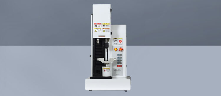
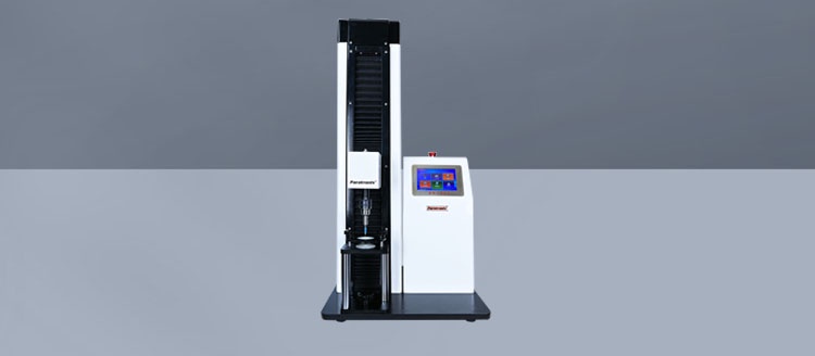

A bone screw torsion tester measures how an orthopedic screw responds when rotational force is applied in a controlled way. The central outputs are usually torque, angular displacement, torsional stiffness, and the point and mode of failure. Together, these measurements show whether a screw can transmit insertion torque without permanent damage, how much it twists under load, and how it ultimately fails when torque continues to rise.
For implant developers, quality teams, and researchers, the value of this test is not limited to finding a single “maximum torque” number. A screw can withstand a high peak torque yet still show excessive angular deformation, inconsistent behavior between samples, damage at the drive recess, or failure in a location that creates a clinical or manufacturing concern. A useful torsion test therefore records the full torque-versus-rotation response, not simply the highest force reached.
The core measurements during a torsion test
A typical Bone Screw Torsion Tester fixes one end of the test specimen and rotates the other at a controlled rate. Depending on the test setup, the screw may be gripped at its shank, threaded region, head, or drive feature. The instrument continuously captures the mechanical response as rotation progresses.
Torque
Torque is the rotational force required to turn the screw. It is usually the first measurement people associate with torsion testing because it relates directly to whether the implant can resist twisting during insertion or removal.
Several torque values may matter during one test:
- Torque at a defined rotation angle: useful for comparing how different designs resist twist before severe deformation begins.
- Yield or deviation torque: the point where the torque-angle curve begins to depart from its initial linear behavior, suggesting the screw is no longer responding purely elastically.
- Maximum torque: the highest rotational load recorded before a substantial loss of load-carrying capacity or before the test ends.
- Failure torque: the torque associated with fracture, stripping, drive damage, or another defined failure event.
These terms should not be treated as interchangeable. A peak torque might occur before visible fracture, while a failure criterion may be defined by a drop in torque, a specified deformation threshold, or damage that makes the implant unusable. The test protocol needs to state which event is being reported.
Angular displacement
Angular displacement is the amount of rotation applied to the specimen, commonly expressed in degrees or radians. By itself, angle does not tell the whole story, but it gives essential context to torque data.
For example, two screws may reach a similar maximum torque. One may do so after only a small amount of rotation and fracture abruptly. Another may continue rotating substantially while carrying torque, indicating greater torsional ductility or progressive damage. Whether that difference is desirable depends on the device design, material, intended use, and applicable test method. In either case, the rotational history reveals behavior that a single peak value would hide.
Torsional stiffness
Torsional stiffness describes resistance to rotational deformation. It is commonly derived from the slope of the initial, approximately linear part of the torque-angle curve. A steeper slope indicates that more torque is required to produce a given angular rotation.
This property is useful when engineers are comparing design changes such as core diameter, thread geometry, cannulation, material condition, or transitions between the shaft and head. A cannulated screw, for instance, removes material from the central section. The resulting effect on stiffness and failure behavior cannot be inferred only from the outside diameter; it must be measured under a defined test arrangement.
Stiffness also helps distinguish a screw that is genuinely strong from one that merely reaches a high torque after large rotational deformation. In product development, both characteristics may need to be understood because excessive twist can alter fit, damage the driver interface, or create uncertainty about the implant’s condition before placement is complete.
Yield, permanent deformation, and failure behavior
As rotational loading increases, a screw may pass from elastic behavior into permanent deformation. In the elastic range, unloading would allow the part to return close to its original position. Beyond that range, the screw may retain twist, lose dimensional accuracy, or become more vulnerable to fracture.
A torsion tester can identify this transition from the changing shape of the torque-angle curve, provided the method defines how yield or offset behavior is calculated. The instrument may also be used to document the final failure mode. Typical observations include:
- Fracture through the shank or threaded section
- Fracture near a geometric transition, such as beneath the head
- Failure around a cannulation or cross-hole
- Stripping, rounding, cracking, or deformation of the drive recess
- Slippage in the test fixture, which is a setup problem rather than a valid specimen failure
The location of failure often has more diagnostic value than the peak torque alone. A repeated fracture at the same feature may point to stress concentration, machining effects, surface defects, heat-treatment variation, or a fixture arrangement that does not represent the intended loading condition.
Why the torque-angle curve matters more than one reported number
A torsion test should generate a curve, not merely a pass/fail display. The curve shows how torque develops as the implant is rotated and allows the evaluator to see stiffness, yield, peak load, torque drop, and post-yield behavior in one record.
Consider two hypothetical curves. The first rises smoothly and nearly linearly, reaches a peak, then drops sharply when the screw fractures. The second rises less steeply, shows a gradual departure from linearity, and continues through a broad region of rotation before torque declines. Both may produce a similar maximum torque, yet they represent different mechanical responses. A design team may need to investigate the second curve for excessive deformation, while a quality team may scrutinize the first for brittle or sudden failure behavior.
The curve is also helpful for detecting inconsistent testing. Unexpected noise, steps, or short torque drops can result from grip movement, backlash, improper alignment, damaged adapters, or specimen seating issues. Without reviewing the trace, a questionable test may be reduced to a peak value that appears credible but does not describe a valid measurement.
What the tester does not measure on its own
A Bone Screw Torsion Tester assesses controlled rotational loading. It does not independently establish every aspect of implant performance. This distinction matters when interpreting results for device development or release testing.
Insertion performance in bone, for example, depends on bone density, pilot-hole preparation, thread design, insertion speed, driver engagement, lubrication or contamination, and surgical technique. A torsion fixture can measure the structural capacity of the screw under rotational load, but it does not reproduce all of those clinical variables. Likewise, a high torsional failure torque does not demonstrate fatigue resistance, bending strength, axial pullout performance, corrosion resistance, biocompatibility, or compatibility with a particular plate and driver system.
The torsion result should therefore be read as one part of a broader verification strategy. It answers a focused question: under the defined rotational boundary conditions, how does the screw resist twist and how does it fail? It should not be used to make claims beyond that question.
Test setup can change the meaning of the result
Mechanical data from implant testing is only comparable when the sample preparation, fixture design, loading rate, gripping length, and failure criteria are controlled. In torsion testing, the fixture is especially important because an orthopedic screw is not a simple uniform rod.
The head, drive recess, threads, tapered sections, flutes, and cannulation can each affect where load is introduced and where failure develops. If the specimen is clamped too close to a transition, the fixture may create a nonrepresentative stress concentration. If the grip does not prevent rotation, apparent angular displacement can include fixture slip rather than deformation of the screw. If the driver interface is being evaluated, the selected driver and engagement depth need to reflect the intended condition.
Loading rate also deserves attention. A rapid rotation rate may be appropriate for one method or development screen, while a slower rate may offer clearer observation of yield and progressive damage. Neither choice is automatically correct without reference to the procedure being followed. The useful question is whether the rate, sample condition, and endpoint are documented well enough that another test can reproduce the result.
How different users apply the measurements
During early design work, torsion testing is often used comparatively. Engineers may assess whether a revised core diameter, different alloy condition, new cannulation profile, or modified drive geometry changes stiffness and failure location. The goal is frequently to understand the tradeoff created by the design change, rather than simply to select the sample with the highest recorded torque.
For manufacturing and quality control, the same test can be used to monitor consistency. A shift in the torque-angle response, even when all samples remain below a formal failure threshold, may reveal changes in raw material, machining, surface treatment, heat treatment, or assembly. Trend evaluation is more informative when the test method and fixture condition remain stable.
For regulatory and verification work, the tester supplies documented mechanical evidence under a defined protocol. The emphasis shifts toward traceability: instrument calibration, sample identification, fixture details, raw data retention, calculation method, and clear acceptance criteria. A well-run test provides a defensible record because another reviewer can understand what was loaded, how it was loaded, and how the reported values were derived.
Questions to ask when reviewing torsion-test results
Before relying on a report, readers should look beyond the maximum torque column. A concise review can begin with these questions:
- Was torque plotted against angular displacement for every specimen, or is only a peak value available?
- Where did each specimen fail, and was the failure mode consistent?
- Did the fixture prevent slippage and unwanted bending?
- What part of the screw was constrained, and how does that relate to the intended use condition?
- Was the drive connection tested as part of the assembly, or was the screw body isolated?
- How were yield, maximum torque, and failure defined in the procedure?
- Are the compared samples tested using the same specimen conditioning, rotational rate, fixture, and data-processing rules?
These questions are particularly important when comparing data from different laboratories or suppliers. A number that appears directly comparable may represent a different effective length, grip method, endpoint, or driver configuration. The test instrument can be highly accurate while the comparison remains misleading because the boundary conditions are different.
Choosing a tester around the measurement task
Selection should begin with the screw family and the intended decision. A system used for small, delicate screws needs appropriate low-torque sensitivity, stable resolution, and fixtures that do not damage or overwhelm the specimen. Larger trauma or orthopedic fixation screws may require greater torque capacity and more robust grips. Choosing a broad-range machine without sufficient resolution at the expected load can obscure meaningful differences near yield or early damage.
Fixture adaptability is often as important as the base machine. A laboratory may need interchangeable holders for different diameters, head designs, cannulated constructions, and driver interfaces. The test software should preserve synchronized torque and angle data, identify the relevant calculated values, and allow operators to review the curve rather than relying solely on an automated result.
The most useful torsion test is one that links a clear mechanical measurement to a defined decision: comparing designs, qualifying a process, investigating a failure, or verifying a device requirement. When torque, angle, stiffness, and failure mode are considered together, the result becomes more than a strength figure. It becomes a practical description of how the implant screw behaves when rotation places its structure under stress.
Leave A Reply
Search by Keywords