




Recent Posts
 When ASTM F1306 is suitable for laminated film puncture testingSep 21, 2026
 Selecting a laminated film puncture force tester for low-force filmsSep 21, 2026
 Which standards should an ampoule break force tester support?Sep 20, 2026
 Using a Leakage Tester to Meet ISO 11607 Package Integrity RequirementsSep 20, 2026
 Using Leak and Seal Strength Tests for Medical Pouches and Sterile Barrier SystemsSep 18, 2026


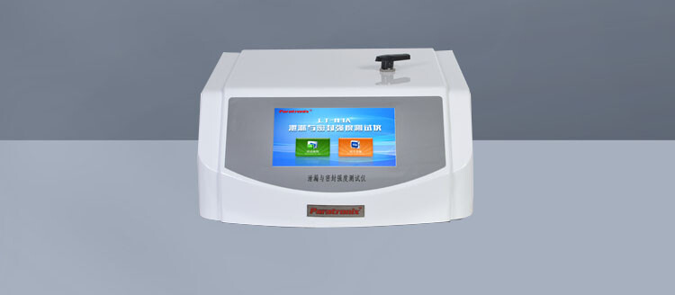
ASTM F1306 is suitable when the question is whether a flexible barrier film or laminate can resist a concentrated puncture event under controlled laboratory conditions. It is especially relevant when failure is likely to begin at a small contact point: a sharp product edge, a corner of a medical device, a rigid inclusion in a pouch, handling damage, or localized loading during conversion and distribution. The method is designed to characterize puncture resistance of flexible barrier materials by driving a specified probe through a clamped specimen and recording the resulting force-displacement behavior.
For laminated films, this controlled event is useful because the laminate does not behave as a single uniform layer. A surface web may stretch, a tie layer may transfer stress, an aluminum foil layer may crack, and a sealant layer may continue to deform after another layer has already failed. ASTM F1306 provides a repeatable way to compare that combined response, provided that the test configuration reflects the material condition and the comparison being made.
Situations Where ASTM F1306 Fits the Material Question
The method is a strong choice when puncture resistance is a meaningful part of package integrity but the package itself is not the test article. This commonly includes rollstock films, lidding materials, sachet structures, pouch webs before conversion, and multilayer barrier laminates used in pharmaceutical, food, and specialty packaging. It is most useful when the objective is to compare material constructions, monitor consistency between production lots, evaluate the effect of a process change, or investigate a localized damage mechanism.
A laminated film puncture result is particularly informative when a change has been made to one part of the structure. Examples include replacing a base film, changing foil temper or thickness, adjusting adhesive coating conditions, modifying a barrier coating, changing orientation in a polymer layer, or reducing total gauge. A simple thickness comparison cannot show whether the revised construction has retained resistance to a localized intrusion. ASTM F1306 can reveal a shift in peak force, energy to puncture, displacement at failure, or the shape of the force-displacement curve.
The method also fits incoming-material verification when the purchase specification identifies a puncture-related requirement and the supplier and receiving site use an aligned test setup. Alignment matters because a reported puncture force has limited meaning without the probe geometry, specimen support, test speed, conditioning approach, and material direction used to obtain it. Two laboratories can test the same laminate and obtain different values if these elements differ.
What the Test Actually Represents
ASTM F1306 represents a controlled penetration event, not every form of package damage. The specimen is clamped over an opening, and a probe moves through it at a defined rate. The instrument captures the resistance as the material deflects and then ruptures. Depending on the selected procedure and the test objective, the result may emphasize the maximum force before penetration, the energy absorbed during penetration, or both.
Peak force answers a narrow but important question: how much concentrated load did the film withstand at its highest resistance point? Energy adds another dimension because it accounts for the work absorbed as the material deflects. Two laminates can show similar maximum force while behaving very differently. A stiff foil-based laminate may reach a high force and fail with little displacement. A polymer-rich structure may deform substantially and absorb more energy before the probe passes through. Neither response is automatically superior. The meaningful response depends on the damage mechanism being controlled.
For a package exposed to a brief contact from a pointed object, peak force may be the closer screening value. When the material must tolerate deformation around an irregular object, energy and displacement can be equally important. Reviewing only one number can hide a construction change that shifts the failure mode from ductile stretching to abrupt fracture.
Why Laminates Need More Than a Single Result
Puncture in a laminate is often a sequence rather than one instantaneous event. The outer layer may yield first, followed by delamination, foil cracking, barrier-coating fracture, or final penetration through the sealant layer. A force-displacement trace may show shoulders, multiple peaks, or a sudden drop followed by continued resistance. These features should be examined when they recur, especially after a formulation, adhesive, or curing change.
A lower peak does not always indicate that every layer has become weaker. It can result from earlier crack initiation in a brittle layer, reduced interlayer adhesion, lower orientation, altered moisture content, or a different interaction between the probe and the surface. Conversely, a higher peak can arise from greater stiffness while the laminate becomes less tolerant of repeated flexing. ASTM F1306 is therefore well suited to controlled comparison, but it should be interpreted alongside the known construction and anticipated damage mechanism.
Layer order also affects the result. Testing from the printed or external side can produce a different response from testing through the sealant side. A hard outer polyester layer, foil layer, or coating may resist initial indentation differently from a softer polyethylene sealant surface. Where the package can encounter puncture from both directions, testing one orientation alone leaves an unexamined failure path. The reporting direction should be fixed and retained with the material specification.
When ASTM F1306 Is Not the Complete Answer
The standard is not a substitute for finished-package testing when seals, gussets, folds, forming stresses, product geometry, or headspace govern the failure. A pouch may pass material puncture testing and still fail when a sharp product corner is driven into a folded area near a seal. Likewise, an unsupported package dropped onto a protrusion experiences impact dynamics, package motion, and product movement that are not reproduced by a slow, clamped-film test.
ASTM F1306 should not be treated as a direct measure of seal strength, tear propagation resistance, flex-crack resistance, abrasion durability, or barrier retention after damage. These properties interact with puncture performance, but they are not interchangeable. A film can resist a probe yet tear readily after a nick. Another structure can tolerate a small puncture load but retain good resistance to crack growth. Selecting the method based solely on the word “durable” often leads to a test program that answers the wrong question.
For highly elastic stretch films, very thin unsupported webs, materials with large surface texture, or laminates that slip in the clamp, the basic setup may require careful review before results are used for specification decisions. The clamp condition must prevent specimen movement without introducing pre-damage or unrealistic edge stress. If the material wrinkles, creeps, or tears at the clamp rather than under the probe, the measured value does not describe central puncture resistance.
Test Configuration Changes the Meaning of the Number
Probe geometry is one of the most consequential variables. A rounded probe spreads load across a larger area and emphasizes deformation before rupture. A sharper tip concentrates stress and can expose brittle fracture or weak local layers sooner. Results from different probe shapes should not be placed in one trend chart as though they were directly equivalent. Each geometry creates a different damage condition.
The specimen support opening also influences deflection and stress distribution. A larger unsupported area allows more stretching before the probe breaks through; a smaller opening can constrain the material and raise apparent resistance. Test speed affects viscoelastic polymer layers, particularly when comparing materials with different stiffness or relaxation behavior. Conditioning affects moisture-sensitive substrates, coatings, adhesives, and certain barrier structures. Even the side facing the probe can change the initiation mechanism.
Building a Useful Comparison
ASTM F1306 is most defensible when the comparison is deliberately narrow. Compare equivalent material directions, the same probe and fixture, the same conditioning regime, the same test side, and specimens prepared in the same way. When a film is printed, coated, corona treated, metallized, or laminated after extrusion, record the tested surface and process state. A result from unprinted web cannot automatically be assigned to a printed laminate if ink, varnish, or curing conditions alter the surface response.
Specimen preparation deserves attention because localized defects are often the reason for testing. Avoid cutting samples through visibly creased, folded, or edge-damaged areas unless the investigation is specifically about those defects. At the same time, do not remove every imperfection from an evaluation intended to represent commercial material. The sampling plan should match the question: material capability, process uniformity, damage investigation, or qualification of a revised construction.
Replicate results should be reviewed as a pattern, not reduced immediately to an average. A wide spread can indicate naturally variable film structure, inconsistent thickness, intermittent adhesion loss, coating defects, or specimen handling damage. A single low result may reflect a visible flaw, but repeated low values in one web position or direction warrant closer examination. Recording observations of whitening, delamination, foil cracking, pinholing, or layer separation adds context that force values alone cannot provide.
Interpreting Failure Modes Alongside Force and Energy
For high-barrier laminates, a visibly intact surface after loading does not prove that barrier function remains intact. A foil layer or brittle coating can develop a crack before the full laminate is punctured. Where preservation of barrier performance is central to the application, puncture testing can serve as a screening tool, followed by an appropriate examination or property test to determine whether the barrier layer remained functional after the imposed event.
Delamination is another condition that can be missed when only the final puncture force is reported. A structure may show substantial force because one layer continues carrying load after bond failure. If the intended application involves forming, flexing, or repeated handling, that internal separation can matter even when the ultimate puncture result appears acceptable. Cross-sectional inspection, controlled peel evaluation, or visual analysis of the failed specimen may clarify whether rupture occurred through the full structure or along an interface.
A sudden force drop followed by a second rise is not automatically an instrument issue. It may indicate partial layer failure, a crack in a foil component, or movement after initial rupture. Conversely, irregular traces can arise from slipping clamps, off-center probe contact, specimen wrinkles, or a damaged probe tip. Reviewing the raw curve and the failed specimen together prevents a valid material signal from being discarded, and prevents a fixture problem from being treated as a laminate defect.
Using the Method in a Controlled Material Specification
A puncture requirement becomes useful only when the test conditions are written with enough detail to reproduce the result. The specification should identify the applicable ASTM F1306 procedure, probe arrangement, fixture opening, test rate, conditioning expectation, specimen orientation, test surface, reported property, and acceptance logic. A requirement stated only as “minimum puncture force” leaves too much room for variation between laboratories and over time.
For development work, reporting both force and energy often gives a clearer basis for selecting between constructions. For routine release testing, a focused parameter may be sufficient after the failure mode and critical damage condition are established. The decision should reflect the product hazard rather than the convenience of a single number. Where a sharp, rigid item is the known threat, the selected probe and test direction should represent that contact as closely as the method allows.
ASTM F1306 is therefore suitable when the need is to measure and compare controlled puncture resistance of flexible laminated film, with the limits of the method kept visible. It becomes especially valuable when test conditions are fixed, failure surfaces are examined, and the reported result is connected to a defined material or packaging damage mechanism rather than treated as a universal measure of package strength.
Leave A Reply
Search by Keywords