




Recent Posts
 How Does a Plastic Film Puncture Tester Work?Nov 04, 2026
 Why Do Thin Film Thickness Readings Vary Between Measurements?Nov 04, 2026
 What Is a Thin Film Thickness Tester and What Can It Measure?Nov 04, 2026
 From Slip Angle to Static Friction: How Inclined Plane Testing WorksNov 03, 2026
 What Does a Luer Taper Comprehensive Performance Tester Measure?Nov 03, 2026
Plastic films used in packaging must withstand sharp edges, handling, and transportation without compromising product protection. How can manufacturers measure their resistance to puncture?
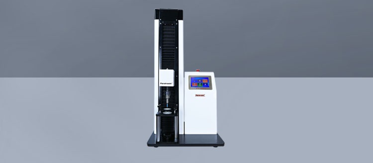
Plastic film puncture test equipment presses a probe into a clamped sample and records the force as the material stretches, yields, and eventually fails.
The resulting force-displacement curve helps manufacturers compare films and monitor quality, but meaningful decisions depend on consistent test conditions and a method suited to the application.
What Does a Plastic Film Puncture Tester Measure?
A puncture tester measures how a film responds when a probe applies concentrated force over a small area. Most systems record force against probe displacement.
The maximum force indicates the greatest load recorded during the test. Depending on the method and failure behavior, it may represent puncture resistance or a peak before penetration.
Displacement shows how far the probe moves from a defined starting point. The curve can reveal stretching, yielding, tearing, or multiple failure events in layered materials.
Some systems calculate energy from the area under a specified portion of the force-displacement curve. This value depends on the integration limits and test procedure.
No single number describes every aspect of performance. A film with a high peak force may behave differently from one that stretches extensively before failure.
For packaging teams, the most useful result is a repeatable measurement linked to a specific risk, such as contact with a sharp product edge or protruding component.
How Does the Testing Process Work?
Although instrument designs vary, the basic process follows the same sequence: prepare a representative specimen, secure it, move a probe, and record the response.
1. Prepare the specimen. Cut samples large enough for the fixture and avoid creases, scratches, or contamination unless those conditions are part of the investigation.
Record material identification, film structure, thickness, sampling location, and conditioning conditions. These details make it possible to investigate differences between rolls, batches, or suppliers.
2. Clamp the film. The specimen is held over an opening using a fixture that controls the exposed test area and limits movement during loading.
The film should be mounted consistently, without unintended wrinkles or excessive tension. Slipping or uneven clamping can change the curve and invalidate a comparison.
3. Position the probe. A probe attached to the moving test system is aligned with the exposed film. Its shape and dimensions must match the selected method.
4. Apply force. The instrument drives the probe toward the specimen at the prescribed speed. A load cell measures force as the film deforms.
5. Record the result. Software plots force against displacement and identifies values defined by the method, such as maximum force or displacement at a specified event.
6. Review multiple specimens. Individual results are examined for anomalies before calculating a summary. The required specimen count should come from the method or validation plan.
An operator should also inspect the tested film. A slipped specimen, damaged edge, or unusual tear pattern may explain a result that the numerical output alone cannot.
What Does the Force-Displacement Curve Reveal?
At the beginning of a test, force typically increases as the probe contacts and stretches the film. The initial curve depends on geometry and contact detection.
A steep rise can indicate substantial resistance to deformation under the chosen conditions. A gradual rise may indicate greater deformation before the same force is reached.
Near the maximum, the material may yield, tear, or experience local penetration. The precise event should be determined from the test definition and specimen inspection.
A sudden force drop often accompanies a failure event, but it does not automatically prove complete penetration. The probe may continue interacting with remaining material.
Multilayer structures can produce several peaks or changes in slope as individual layers stretch or fail. Such curves are useful for investigation, not automatic layer identification.
When comparing curves, check both the peak and the displacement at relevant events. Two materials can reach similar peak forces while deforming very differently.
Energy calculations require particular care: changing the endpoint, baseline, or calculation method can change the reported value even when the underlying curve is identical.
Which Test Conditions Affect Puncture Results?
Probe geometry is critical. A pointed probe concentrates force differently from a rounded probe, so results obtained with different tips should not be compared directly.
Probe diameter, tip condition, and alignment also matter. Wear or damage can alter contact with the film, while misalignment may introduce inconsistent loading.
Test speed influences how many polymers deform and fail. A result obtained at one speed may not predict performance at a substantially different loading rate.
The clamp opening determines the unsupported area available to stretch. Fixture dimensions and clamping pressure must remain consistent when comparing materials or monitoring production.
Thickness affects resistance, but dividing force by thickness does not automatically produce a comparable material property. Layer structure and failure mode can also change with thickness.
Temperature, humidity, and conditioning time can influence film behavior, particularly for moisture-sensitive materials. Follow the selected procedure and record any deviations from its conditions.
Film orientation and sampling location may matter, especially for oriented or nonuniform materials. Sample across the roll or production lot according to a defined plan.
Finally, confirm the instrument's force and displacement measurement performance. An unsuitable load range, poor zeroing, or overdue calibration can undermine otherwise careful testing.
Which Standard Should You Use?
Choose the test method before selecting an instrument or setting acceptance limits. The relevant choice depends on the material, intended application, customer requirements, and failure mechanism.
ASTM D5748 describes a slow-rate penetration resistance test for stretch wrap film using a rounded probe. Its scope and prescribed conditions should guide its application.
ASTM F1306 addresses slow-rate penetration resistance of flexible barrier films and laminates. Consult the current standard for specimen preparation, apparatus, calculations, and reporting requirements.
These methods are not interchangeable simply because both use a probe. Their specified equipment and procedures may differ, and results should be labeled with the method used.
Other standards, customer specifications, or internal methods may be appropriate for a particular product. Confirm that the method's scope covers the material and decision being made.
Using equipment described as compatible with a standard is not sufficient by itself. The complete procedure, including fixtures, settings, calibration, and reporting, must meet applicable requirements.
Obtain the current official version of any standard before testing. Where a customer specifies an edition or deviation, document that agreement alongside the reported results.
How Should You Interpret and Compare Results?
Start by checking that samples were tested using the same method, probe, fixture, speed, and conditioning. Differences in setup can be larger than differences between materials.
Review individual measurements as well as the average. A film with an acceptable mean but wide variation may present inconsistent protection across a production lot.
Report the number of valid specimens and a measure of variation, such as standard deviation, when appropriate. Explain exclusions and retain the associated test records.
For example, two films might both average 12 newtons under one procedure, while one has a much wider spread. The average alone would hide that distinction.
Likewise, a higher peak force does not guarantee better package performance. A stiff film may resist initial loading yet tear differently after contact with a sharp edge.
Compare displacement and curve shape with the expected packaging risk. Where repeated contact, impact, or abrasion matters, add tests that address those distinct mechanisms.
Set acceptance limits using representative production data, measurement variability, and evidence from package performance. Avoid adopting another company's numerical limit without confirming equivalent conditions and requirements.
When a lot falls outside its limit, verify setup and specimen validity first. Then investigate material, processing, and sampling factors before deciding on disposition.
Can a Lab Puncture Test Predict Real Packaging Failures?
A laboratory test creates a controlled comparison; it does not reproduce every hazard encountered during filling, transport, storage, or use. Results are indicators, not guarantees.
Actual damage may depend on product shape, package tension, seal placement, temperature, vibration, and repeated impacts. A single probe test cannot represent all these variables.
Use puncture testing alongside application-specific package trials. For example, evaluate filled packs containing the actual product and run distribution testing appropriate to the supply chain.
When laboratory rankings disagree with field performance, examine probe geometry, loading speed, and failure mode. The test may measure a different hazard from the one causing damage.
Correlating controlled measurements with documented failures helps identify useful limits. Recheck that relationship when the film structure, product geometry, or distribution environment changes.
For pharmaceutical or high-barrier packaging, a puncture result should also be considered alongside package integrity and barrier requirements. Mechanical resistance alone does not establish those properties.
How Do You Choose Plastic Film Puncture Test Equipment?
Begin with the methods and materials you need to test. Confirm that the available probes, fixtures, travel, and speed range support each intended procedure.
Select a load cell with a suitable measurement range for expected forces. Ask about verified accuracy across the working range, not just the maximum instrument capacity.
Check whether the fixture holds thin, flexible, or slippery specimens consistently. Easy specimen alignment and repeatable clamping can reduce operator variation during routine quality control.
Review how the software defines contact, peak force, displacement, and energy. It should provide the calculations and raw data needed for your method and investigation workflow.
For regulated or customer-audited environments, assess access controls, traceability, data retention, and export options against your organization's requirements. Confirm capabilities before purchasing.
Consider calibration support, replacement probes, maintenance, operator training, and local service. These practical factors affect the reliability and total cost of the instrument over time.
Before purchase, provide representative samples and request a demonstration using your intended method. Examine repeatability, curve quality, specimen handling, and reporting rather than relying on specifications alone.
Paratronix Instruments Co., Ltd. supplies packaging testing instruments and solutions for plastic packaging, pharmaceutical packaging, and high-barrier materials. Discussing the application can help establish suitable equipment requirements.
Conclusion
A plastic film puncture tester works by driving a defined probe into a clamped specimen while measuring force and displacement. The resulting curve captures more than peak load.
Reliable comparisons require a suitable method, controlled conditions, representative sampling, and attention to variability. Pair laboratory results with package-level evidence before setting specifications or predicting field performance.
Leave A Reply
Search by Keywords