




Recent Posts
 From Slip Angle to Static Friction: How Inclined Plane Testing WorksNov 03, 2026
 What Does a Luer Taper Comprehensive Performance Tester Measure?Nov 03, 2026
 Luer Connector Testing: What to Check Under ISO 80369-7Nov 03, 2026
 ISO 80369-7 Air Leakage Testing: What to Check in a Luer TesterNov 03, 2026
 What Does a Luer Taper Air Leakage Tester Measure in Medical Connectors?Nov 03, 2026
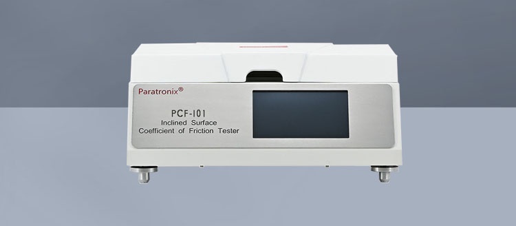
When a packaging film slips too easily during handling, or resists sliding enough to disrupt movement through equipment, an inclined-plane test can help characterize the surface interaction. An Inclined Surface Coefficient of Friction Tester gradually raises one surface until a specimen begins to slide against another. Under an ideal force balance, the static coefficient of friction is estimated as the tangent of the slip angle: μs = tan θ.
That relationship is useful only when the contact pair and test conditions are defined. The result describes the onset of sliding for the surfaces tested together; it is not an intrinsic property of one film alone, nor does it automatically predict performance on a packaging line. Surface orientation, conditioning, loading and the way motion is detected can all change the reported value.
From slip angle to friction coefficient
Consider a sled resting on a plane inclined at an angle θ to the horizontal. Its weight acts vertically, but can be resolved into two components: one parallel to the plane, which tends to pull the sled downhill, and one perpendicular to the plane, which creates the normal force between the surfaces.
For a simple, freely resting sled, the parallel component is mg sin θ and the normal component is mg cos θ, where m is the sled mass and g is gravitational acceleration. At the threshold of sliding, the limiting static friction is represented by μsmg cos θ. Equating the forces gives:
mg sin θ = μsmg cos θ
μs = tan θ
The mass and gravitational acceleration cancel in this idealized calculation. That does not mean sled mass can be ignored in practice. Changing the load can alter contact area, deform a soft specimen or affect adhesion, so results should be compared at the same specified loading conditions.
Use the angle in the correct calculator mode. For example, a slip angle of 30° corresponds to tan 30°, or approximately 0.577. Friction coefficients are dimensionless; the angle itself should still be retained in the test record so the conversion can be checked.
Where the equation becomes an approximation
The tangent relationship assumes a quasi-static increase in angle, a correctly measured plane angle, and no significant forces other than weight, normal force and friction. Acceleration from rapid tilting, vibration, a cable pulling on the sled, or a specimen catching on an edge can disturb that balance. Flexible films can also wrinkle or deform, making the contact less uniform than the model assumes.
The calculation therefore converts an observed slip angle into an apparent static coefficient for a defined arrangement. It should not be treated as an exact material constant independent of apparatus and method.
What is actually sliding?
Before comparing results, identify both contacting surfaces and the direction of contact. A film may be tested against another piece of the same film, a different packaging material or a specified reference surface. “Film coefficient of friction” is incomplete unless the report also identifies what touched the film.
Orientation matters for multilayer packaging. The sealant side and the outside print or coating side can have different surface characteristics. A high-barrier laminate can also behave differently when tested film-to-film than when its outer surface contacts a machine component. Record the side facing the plane and the side facing the sled, along with any relevant machine direction or transverse direction specified by the method.
Surface condition deserves the same attention. Slip additives, coatings, printing, dust and handling residue can affect the interface. Time after manufacture, storage conditions and contact with other materials may also influence the surface presented to the test. These factors are particularly important when two lots have the same nominal construction but produce different slip angles.
Setting up a defensible measurement
The applicable standard or internal procedure should govern specimen preparation and instrument settings. The following sequence explains the decisions behind the measurement rather than replacing a prescribed method.
- Define the contact pair. Identify both materials, their contacting faces and orientation. Select representative specimens, avoiding folds, obvious damage and areas that do not belong to the surface being evaluated.
- Condition and handle consistently. Follow the specified temperature, humidity and conditioning time. Avoid touching the test areas; contamination introduced during preparation can obscure differences between materials.
- Prepare the plane and sled. Check that mounting surfaces are clean and that films are secured as the procedure requires. The contact area should be flat without stretching, trapped folds or loose edges that could catch during tilting.
- Set the prescribed load and motion. Use the specified sled or equivalent loading arrangement, verify its condition, and set the tilt rate according to the method. Start from the prescribed initial position and avoid disturbing the specimen before the measurement.
- Determine the slip point. Raise the plane and record the angle at the method-defined onset of movement. Distinguish sustained sliding from a brief twitch caused by vibration or localized relaxation.
- Repeat and document. Test the required number of specimens or positions, using fresh contact areas where the method requires them. Record individual angles and calculated coefficients, not only the average.
Some instruments detect movement automatically; others rely on an operator or a defined visual endpoint. These approaches can produce different readings when motion begins gradually. A detection threshold, response delay or sampling interval may also shift the recorded angle. The chosen endpoint and instrument settings belong in the test record, especially when results will be transferred between laboratories.
Verify the angle, not just the display
A numerical readout is only useful if the plane angle is referenced correctly. Check zero position and angle indication using the laboratory’s calibration or verification procedure. The plane should move smoothly, without noticeable jerks or backlash that could initiate motion prematurely or cause the indicated angle to lag the actual position.
Also inspect the sled and specimen fixtures. A warped contact face, uneven mounting tape or residue left by a previous sample can create inconsistent contact. Cleaning should follow a controlled procedure: an unsuitable solvent or abrasive treatment can change a reference surface rather than restore it.
Reading the result without overextending it
A higher slip angle corresponds to a higher calculated static coefficient, provided the same conversion and comparable conditions are used. It indicates greater resistance to the start of relative motion in that particular arrangement. It does not by itself measure how much force is needed to keep the surfaces moving.
Static and kinetic friction are different endpoints. An inclined-plane onset test primarily addresses static friction. Once the sled is moving, its behavior may depend on speed and other effects; the initial angle should not be reported as a kinetic coefficient unless a relevant method explicitly supports that interpretation.
Nor should an inclined-plane result be assumed interchangeable with a horizontal sled result. A horizontal method typically derives friction from measured pulling force and normal force, while the inclined method derives it from an angle at the onset of motion. Differences in contact geometry, speed, loading, endpoint detection and specimen preparation can produce different results even for nominally identical materials. Compare values across methods only after establishing an appropriate correlation for the intended materials and conditions.
In application, the desired level of friction depends on the job. Low resistance may help a film move over a surface, but excessive slip can affect stacking or positioning. Higher resistance may help retain position while increasing the chance of drag elsewhere. The test provides a controlled comparison of an interface; deciding whether that interface is acceptable requires a separate link to the actual handling conditions.
When nominally similar specimens disagree
A wide spread of angles is itself useful information. Do not immediately discard a high or low result merely because it differs from the average. First check whether the test method permits rejection and whether an observable event, such as a snagged edge, justifies it. Preserve the individual observations so that a preparation problem can be distinguished from genuine material variation.
A repeat test is most informative when only one suspected cause changes at a time. For example, changing both the contacting face and the conditioning period may produce a different result, but it will not show which change was responsible. If the surface is direction-sensitive, prepare separate specimens in each orientation rather than rotating one specimen after its contact area has already been used.
Standards and reporting: establish equivalence before comparing numbers
Inclined-plane friction procedures exist in published standards, but their scope and detailed requirements are not interchangeable. ASTM D202 provides an inclined-plane method for the static coefficient of friction of uncoated writing and printing paper; ASTM D4917 addresses the static coefficient of friction of uncoated writing and printing paper using a horizontal plane. Neither should be presumed suitable for a packaging film solely because it measures friction. Select the standard that covers the material and intended test arrangement, and verify the current edition and contractual requirements before testing.
For plastic film and sheeting, ASTM D1894 and ISO 8295 are commonly cited friction methods using horizontal test arrangements. They should not be described as inclined-plane procedures. If a specification calls for one of these methods, an angle-derived value is not automatically a compliant substitute. An internal inclined-plane method can still be useful for screening, but its relationship to the specified method must be demonstrated rather than assumed.
A report should make the result reproducible: identify the procedure and edition or internal method, instrument and angle verification, specimen materials and contacting faces, conditioning, sled or applied load, tilt rate, endpoint definition, number of measurements, individual results and any deviations. Include both the slip angles and the calculated coefficients, together with the calculation and rounding convention used. Where results support a specification decision, apply the acceptance and rounding rules stated in that specification rather than creating them after the test.
Finally, a result close to a specification boundary needs more scrutiny than a well-separated result. Review repeatability, angle resolution and the laboratory’s measurement uncertainty where available. Because the tangent function is nonlinear, the same angular error does not correspond to the same coefficient error at every angle. Retaining the original angles makes that assessment possible and prevents a rounded coefficient from concealing a meaningful difference.
Leave A Reply
Search by Keywords