




Recent Posts
 From Slip Angle to Static Friction: How Inclined Plane Testing WorksNov 03, 2026
 What Does a Luer Taper Comprehensive Performance Tester Measure?Nov 03, 2026
 Luer Connector Testing: What to Check Under ISO 80369-7Nov 03, 2026
 ISO 80369-7 Air Leakage Testing: What to Check in a Luer TesterNov 03, 2026
 What Does a Luer Taper Air Leakage Tester Measure in Medical Connectors?Nov 03, 2026
A Luer connector can appear to fit correctly and still leak, loosen or separate under conditions relevant to use. ISO 80369-7 addresses these risks through requirements for small-bore connectors intended for intravascular or hypodermic applications. A credible conformance decision depends not only on whether a connector passes individual tests, but also on whether the correct connector configuration, reference components, assembly conditions and applicable standard edition were used.
Leakage and connection security are central checks, but they are not interchangeable. A joint may remain leak-tight during one pressure test yet be vulnerable to separation under an axial load. A locking connection may resist disconnection but still leak because the sealing surfaces are damaged. Each result answers a specific question about the connection, not every question about the finished device.
Establish what is being assessed
ISO 80369-7 is the application-specific part of the ISO 80369 series for connectors used in intravascular or hypodermic applications. Its requirements work alongside other relevant parts of the series, including general requirements and standardized test methods. The applicable edition, amendments and relationship between the standards should be established before a protocol is approved.
That matters because a test method and an acceptance requirement do different jobs. A method describes how a characteristic is evaluated; the application-specific standard identifies the relevant requirements for the connector. A report that cites a test method without identifying the applicable requirement can document an experiment without supporting a clear conformance decision.
Define the item under test with enough detail to reproduce the assessment: male or female connector, slip or lock configuration, material, manufacturing process, and the device or component in which the connector is incorporated. Where the connector is part of a finished device, surrounding features can affect how it is assembled, gripped or loaded. Testing an isolated component is not necessarily equivalent to testing the connector as presented in the finished product.
It is also important to distinguish connector conformance from broader device compliance. ISO 80369-7 does not, by itself, establish that a syringe, infusion set or other finished device meets every applicable safety and performance requirement. Nor does a successful connection with one commercial mating part demonstrate compatibility with every product on the market.
Dimensional fit and the limits of visual inspection
Luer connections rely on specified mating geometry. Dimensions, surface condition and the relationship between the male and female components influence whether the joint can be assembled and whether sealing surfaces engage as intended. Locking features add another functional interface: they help retain the connection but should not be treated as a substitute for the taper’s sealing performance.
Dimensional assessment should use the drawings, gauges and measurement requirements specified in the applicable edition. A connector that looks undamaged or can be joined by hand has not necessarily demonstrated dimensional conformity. Conversely, a measurement taken at an inappropriate location or with an unsuitable gauge may lead to a misleading rejection or acceptance.
The material and manufacturing process deserve attention when interpreting results. Moulding variation, deformation, surface defects and changes in friction can affect assembly and sealing. Where a design has multiple material or manufacturing variants, a rationale is needed for deciding which configurations represent the relevant range. Nominally identical geometry does not automatically mean identical performance if the materials or surrounding structures differ.
Dimensional conformity and functional testing complement each other. Dimensions provide evidence that the connector is manufactured within the specified geometry; performance tests assess how the assembled connection behaves under defined conditions. Passing one category does not eliminate the need to address the other where both are applicable.
Leakage: test the condition, not just the outcome
Liquid leakage testing evaluates whether an assembled connection maintains its seal when exposed to the prescribed liquid-pressure condition. A negative-pressure or air-leakage assessment addresses a different failure mode: air entering the system rather than liquid escaping from it. Depending on the applicable requirements and configuration, both directions of leakage can be relevant.
A leak result depends heavily on how the joint was prepared. The mating component, assembly force or torque, dwell time, test medium, pressure conditions and duration must follow the applicable method. Over-tightening can mask an assembly problem or damage the connector; insufficient or inconsistent assembly can create a failure that is difficult to interpret. Neither is a sound basis for comparing lots.
Leak detection also needs an established decision rule. A visible droplet, a pressure change, or another specified indication must be assessed according to the method being used. Pressure decay alone can be affected by factors outside the connector interface, including fixture leakage, trapped air and temperature change. Before attributing a failure to the specimen, check the integrity of the test circuit and the suitability of the setup.
Leaks should be recorded by location as well as result. Leakage at the mating interface has a different potential cause from leakage at a connection between the specimen and the test fixture. A clear distinction helps prevent an equipment fault from being treated as a product defect—or a product defect from being dismissed as a fixture issue.
Resistance to separation and disconnection
A connection can be exposed to loads from handling, movement or attached tubing. Separation testing examines whether an assembled joint resists the specified axial load under the defined test conditions. The load path matters: a fixture that introduces bending, grips a deformable region or slips during the test can change the stress applied to the connector.
For locking connectors, resistance to unscrewing addresses a related but distinct concern. A joint may remain together under a straight pull yet loosen when subjected to rotational action. The applicable procedure should be used to assess the locking feature; an axial pull test is not a replacement for it.
Assembly conditions are especially important when evaluating retention. The force or torque used to make the joint can influence the load or torque needed to undo it. If specimens are assembled more tightly than the specified method permits, the resulting retention value may overstate performance under the required condition. Conversely, inconsistent assembly can increase scatter and make it difficult to distinguish product variation from test variation.
Failure descriptions should identify what actually happened: taper disengagement, thread disengagement, breakage of a locking feature, fracture elsewhere in the specimen or loss of fixture grip. These events can produce similar instrument readings but call for different corrective actions. A peak force or torque without the observed failure mode provides an incomplete record.
Other performance checks depend on connector design
The applicable ISO 80369-7 requirements also need to be reviewed for characteristics such as resistance to overriding, stress cracking and disconnection by unscrewing, where relevant to the connector design and specified test conditions. These are not interchangeable tests and should not be added or omitted solely because an instrument offers a convenient preset.
For example, a locking feature that rides over its mating thread or otherwise fails to engage as intended presents a different concern from leakage at the taper. A stress-cracking assessment addresses susceptibility to damage under the prescribed conditions; it should not be interpreted as a blanket prediction of resistance to every chemical, cleaning agent or exposure throughout the device’s life.
Likewise, any assessment of non-interconnectability must follow the applicable requirements across the ISO 80369 series. A Luer connector’s intended compatibility within its application category does not justify assuming compatibility with unrelated small-bore connector systems. The relevant standards and risk-management evidence should define what is required.
Reference connectors and test equipment can change the result
Performance tests commonly require specified reference components rather than an arbitrary mating device. Their geometry, condition and identification matter because the reference component forms part of the test system. Wear, damage, contamination or the use of a component intended for a different test can influence sealing and retention. Keep records linking the reference component to the test and control its inspection and replacement.
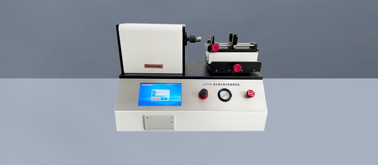
A Luer Taper Comprehensive Performance Tester can support several of these assessments if it can apply and measure the required pressure, axial force, torque and timing conditions with suitable fixtures. The number of functions listed for an instrument is less important than whether each function reproduces the applicable method. A displayed “pass” is meaningful only when the configured limits, sequence and decision rules match the approved protocol.
Before relying on automated results, verify the measurement ranges and calibration status of the relevant sensors, the accuracy of force and torque application, and the ability to maintain the required pressure and timing conditions. Fixture alignment, specimen grip and leak tightness of the test circuit should be checked as part of equipment qualification. Software settings and report templates also need control: a correct test performed against an obsolete acceptance limit can still produce an invalid conclusion.
Not every characteristic is necessarily measured by a single machine. Dimensional gauges, visual examinations, reference components and other equipment may be needed alongside a multifunction tester. The test plan should identify the method and equipment for each requirement rather than assume that one instrument establishes complete conformity.
From individual results to a defensible quality decision
A useful test record connects each result to the exact specimen and conditions that produced it. At a minimum, retain the connector identification and configuration, lot or other traceability information, applicable standard edition, procedure, reference component, equipment identification, assembly conditions, environmental conditions where required, results and deviations. The report should state the acceptance criterion used and whether the observed result met it.
Sampling is another point at which a valid test can become an overstated claim. A small set of passing specimens shows that those specimens passed under the recorded conditions; it does not automatically establish the capability of every production lot. Design verification, process validation and routine release testing serve different purposes, so their sample selection and acceptance decisions should be justified separately.
When a failure occurs, preserve the specimen and relevant test data where practical. Review the failure mode, assembly record, reference component, fixture and instrument status before deciding whether the result is invalid. Retesting should follow a predefined investigation process, not simply replace an inconvenient result with a later pass. If the original result is excluded, the technical basis for exclusion should be documented.
The strongest conformance conclusion is therefore a traceable one: the correct requirements were identified, representative configurations were assessed using controlled methods, and each pass or failure can be linked to an explicit criterion. Testing demonstrates performance under specified conditions; the remaining risks of the finished device and its intended use require their own evidence.
Leave A Reply
Search by Keywords