




What Is A Bone Screw Insertion Tester?
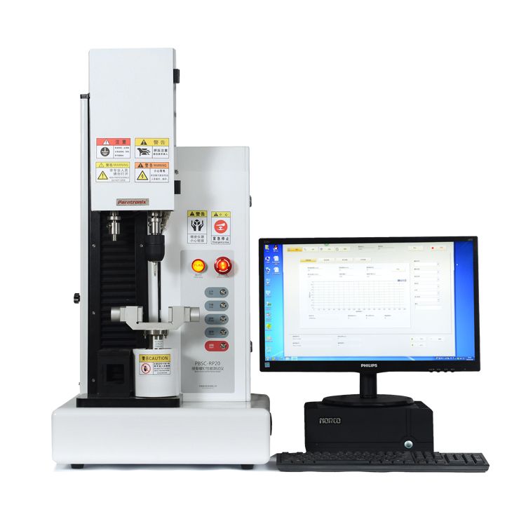
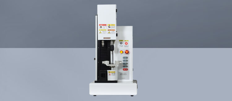
A Bone Screw Insertion Tester is a mechanical testing system that rotates a bone screw into a specified test material while measuring the torque required for advancement. Depending on the configuration and test method, it may also control or record axial force, displacement, rotational speed, and insertion depth. The resulting data help engineers compare designs, investigate manufacturing changes, and characterize how a screw engages a controlled substrate.
ASTM F543 is a standard specification and set of test methods for metallic medical bone screws. Its annexes address several properties, including torsional performance, insertion and removal torque, axial pullout strength, and self-tapping performance. These tests answer different questions: insertion torque describes resistance during placement, while pullout testing measures axial resistance after insertion. A favorable result in one test does not establish performance in every other mode.
The equipment is used by implant manufacturers, research institutions, independent laboratories, and organizations evaluating screw designs or production changes. It supports design verification and comparative development, but a bench test is not a direct prediction of clinical success. Test results depend on the screw, substrate, pilot hole, fixture, and procedure, so meaningful comparisons require controlled and documented conditions.
How ASTM F543 Insertion Testing Works
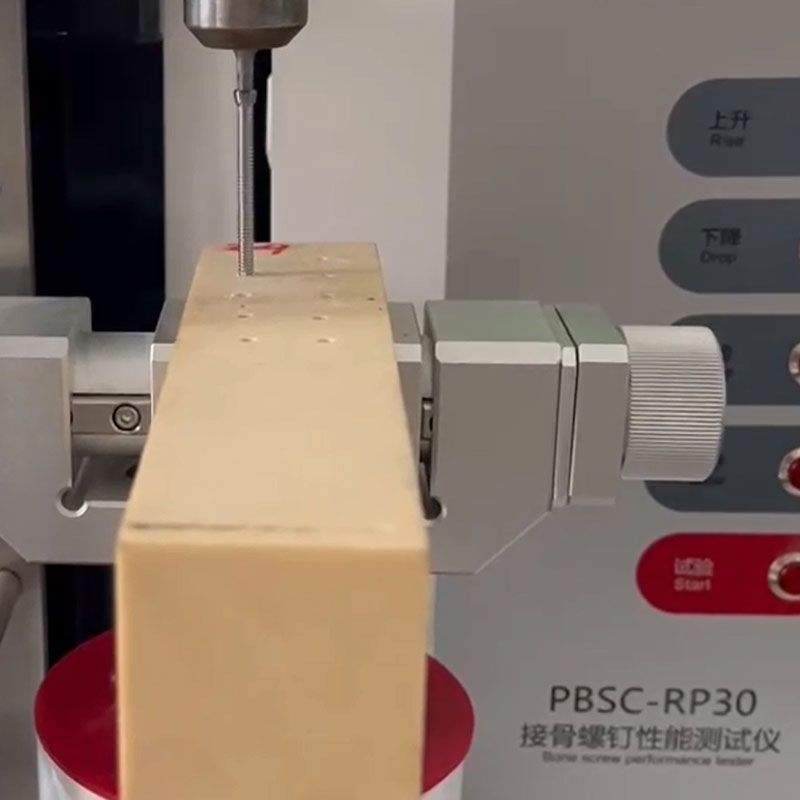
In a typical insertion test, the screw is aligned with a prepared test block and driven at a controlled rotational speed. A torque transducer records resistance as the threads engage the material. The test may also apply a specified axial load or control axial movement, depending on the applicable method and protocol. The operator records the torque curve and the insertion conditions needed to interpret it.
Before testing, define the substrate and its condition, pilot-hole geometry where applicable, screw engagement depth, drive interface, and measurement settings. Synthetic bone substitutes can improve repeatability in comparative studies, while biological bone may be selected for a different research question. Neither substrate should be treated as universally interchangeable with the other. Consult the current applicable ASTM F543 edition for the relevant method and procedural requirements.
Report the screw identification, specimen preparation, equipment configuration, test parameters, and torque results alongside any deviations from the selected method. Peak torque alone can conceal changes in the shape of the curve, such as an abrupt increase during engagement. Retaining the full trace and specimen records makes investigations more useful and helps reviewers distinguish a design effect from a preparation or alignment problem.
Tester Types And Related Mechanical Tests
Equipment ranges from dedicated motorized torque systems to multipurpose mechanical testers configured with appropriate drives, sensors, and fixtures. A dedicated system may suit laboratories focused on routine insertion measurements; a multipurpose platform can be considered when the workload also includes axial testing. In either case, the relevant question is whether the configured system can execute and document the chosen procedure over the required measurement range.
Torsion testing examines the screw under rotational loading and is distinct from measuring torque as the screw advances into a substrate. Axial pullout testing assesses the force needed to withdraw an inserted screw along its axis. Self-tapping evaluation addresses the screw's ability to form its own thread in a test material under the specified conditions. Each test needs suitable fixtures and a separately defined protocol.
For a broader evaluation, plan the sequence and specimen allocation before purchasing equipment. Pullout tests generally require a properly inserted screw and a compatible axial loading arrangement, while other procedures may require separate specimens. Ask suppliers whether changing between methods requires additional sensors, software, grips, or fixture sets. A single platform can reduce equipment duplication, but only if its configured capabilities meet each intended method.
Selecting Equipment For ASTM F543 Applications
Start with the screw sizes, expected torque range, substrate dimensions, and required insertion depths. Specify sensor capacity and usable measurement range so that expected values can be measured with appropriate accuracy without overloading the transducer. Review rotational speed control, axial load or displacement control, travel, alignment, and data acquisition against the written test plan. Do not assume that a nominal maximum capacity guarantees adequate performance at low loads.
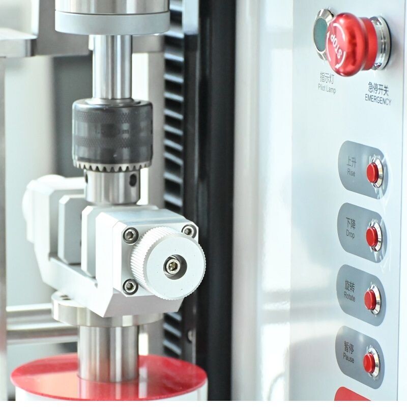
Fixture design matters as much as the headline specifications. The drive must fit the screw interface, hold alignment, and limit unwanted movement, while the substrate holder must resist rotation and accommodate the intended specimen. Ask how the system handles different screw lengths and head geometries, how zeroing is performed, and whether torque and axial data are synchronized. Request a demonstration using representative screws and substrates where practical.
For buyers reviewing application options, paratronix lists the PBSC-RP30 Bone Screw Performance Tester alongside a broader range of torque and multipurpose testing equipment. Discuss the intended ASTM F543 methods with the supplier and request model-specific specifications, fixture details, calibration arrangements, and software outputs. Confirm the configuration against the laboratory's protocol before purchase; the product name alone does not establish conformity to a particular standard edition.
Quality Control And Market Access
A controlled workflow begins with a written protocol and trained operators. Identify each screw and test block, verify the drive and fixture condition, prepare the substrate consistently, and check sensor zero before the run. Record environmental or material-conditioning details when they are relevant to the method. After testing, inspect the screw and substrate for unusual damage and retain raw data so unexpected curves can be investigated.
Calibration and maintenance intervals should follow the equipment manufacturer's recommendations, laboratory procedures, usage, and applicable quality requirements. Maintain traceable calibration records for relevant measurement channels, and check alignment, drive wear, and fixture security routinely. When software, sensors, or fixtures change, assess whether the change could affect results and whether verification or requalification is needed before releasing subsequent data.
ASTM F543 data can form part of a technical evidence package, but using a Bone Screw Insertion Tester does not by itself establish regulatory clearance or market access. Requirements depend on the device, jurisdiction, intended use, and current regulatory expectations. Confirm the applicable standard edition and any recognized deviations with the relevant authority or conformity assessment body, and document how the selected test supports the device's specific claims.
Ownership Costs And Future Trends
Total ownership cost includes the instrument, suitable sensors, screw drives, substrate fixtures, installation, training, and any software or data-export options. Budget for test blocks, calibration, preventive maintenance, replacement parts, and operator time as well. A lower purchase price may not reduce overall cost if frequent fixture changes, limited data handling, or external testing add substantial expense over the planned service life.
Estimate return on investment by comparing expected annual test volume and internal operating costs with the cost and lead time of outsourced testing. Include the time needed to prepare specimens, review traces, maintain equipment, and investigate failures. Consider whether faster access to development data has value for the project, but avoid treating reduced lead time as a guaranteed outcome. Use supplier quotations and actual laboratory workload to build the comparison.
Future purchasing decisions should account for growing interest in traceable digital records, automated test sequences, and equipment that can accommodate changing screw designs. These features are useful only when they support a validated workflow and preserve access to raw measurements. To assess a suitable configuration, provide paratronix with the screw range, planned methods, expected loads, substrate details, and reporting requirements, then review a written proposal against the test protocol.
 Self-Tapping Screw Tester Metrics for Torque, Insertion, and Pull-Out TestingSelf Tapping Screw Tester metrics for insertion torque, stripping torque, seating, and pull-out force. Learn how to achieve reliable fastening tests and stronger quality control.
 Bone Screw Insertion Testing vs. Pullout Testing: What Each RevealsDiscover what a Bone Screw Insertion Tester reveals about torque versus pullout strength. Compare test methods, avoid misleading results, and choose the right equipment for reliable screw testing.
Search by Keywords