




What A Bone Screw Self-Tapping Performance Tester Measures
A bone screw self-tapping performance tester is a mechanical testing system used to characterize how a screw forms a thread and advances into a specified test material. It records axial force and rotational torque during a controlled insertion sequence. The resulting measurements help engineers compare screw designs, investigate manufacturing changes, and document performance under a repeatable set of laboratory conditions.
Self-tapping performance concerns the interaction between the screw cutting features, the prepared hole, and the surrounding material. Axial force acts along the screw axis, while insertion torque resists rotation around that axis. Both signals can change throughout the test, so a single maximum value may not explain whether a design starts cutting readily or maintains stable advancement.
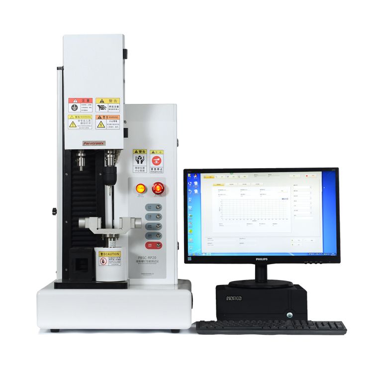
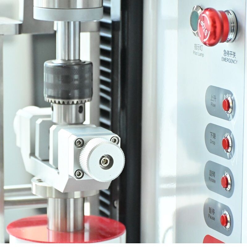
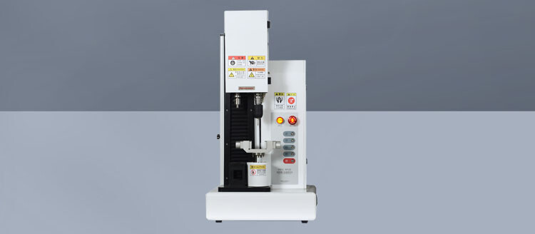
A typical system combines a rotational drive, an axial loading or displacement mechanism, force and torque transducers, a specimen fixture, and software for data acquisition. Depending on the configuration, the equipment may control axial load, axial travel, rotational speed, or a combination of these parameters. The selected method determines which quantities are controlled and which are measured.
This test is distinct from pull-out testing, which assesses resistance to axial extraction after insertion, and from torsional strength testing, which examines screw behavior under applied torque. These methods can complement one another but do not measure the same property. Buyers should define the required tests and fixtures before assuming that one machine configuration can perform all of them.
Measurement Principles And Test Variables
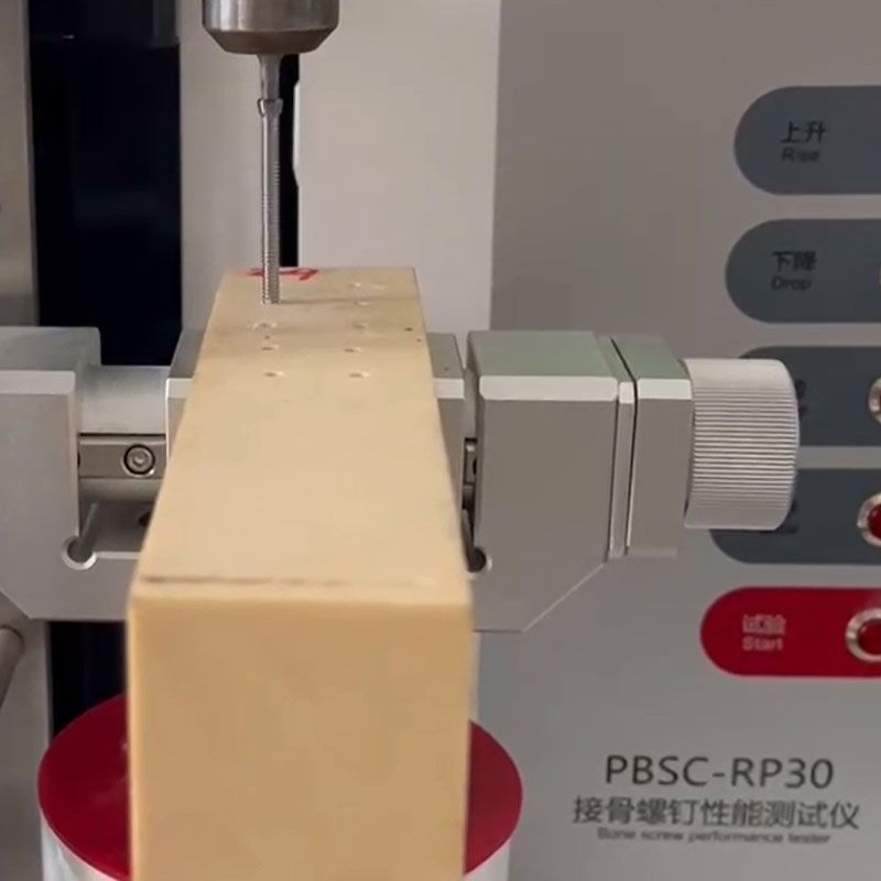
During a test, the screw is aligned with a prepared specimen and driven at a defined rotational speed. The apparatus applies or measures axial loading while the torque transducer captures resistance to turning. Time, rotational position, and axial travel can provide context for the force and torque traces when those channels are available and synchronized.
The torque curve may include initial engagement, thread cutting, and deeper insertion phases. Peak torque, torque at a specified depth, or an average over a defined interval can be useful outputs, provided the calculation window is stated. Force data should likewise be interpreted against the relevant depth or time interval, not reported without the loading conditions that produced it.
Results depend on specimen material, density or grade, hole diameter, hole depth, screw dimensions, and the condition of cutting edges. Rotational speed, axial loading strategy, alignment, and insertion depth also affect comparisons. Lubrication and specimen conditioning should be specified where relevant. A test plan should hold these factors consistent or deliberately vary them as part of an experimental design.
Measurement quality depends on transducer range, calibration, sampling rate, and mechanical alignment. An oversized torque sensor can reduce useful resolution for small screws, while an undersized sensor risks overload. Engineers should also verify that signal acquisition captures brief peaks and that fixture compliance or drive backlash does not obscure the event being evaluated.
Equipment Categories And Configuration Choices
Dedicated screw testing systems are configured around rotational drive, axial motion, and specimen holding for screw-related methods. Their value depends on whether the supplied hardware and software match the intended protocol. A buyer should confirm supported screw sizes, attachment interfaces, specimen dimensions, and the ability to export the raw force and torque data needed for analysis.
A multipurpose mechanical tester may support screw testing when fitted with an appropriate torque drive, sensors, and fixtures. This approach can be attractive for laboratories that also perform other mechanical tests, but interchangeability should be verified in a demonstration. Retrofitting an existing frame may require additional controls, software integration, and method validation.
Configurations also differ in axial control. Some methods require a specified axial load; others call for controlled travel or another prescribed sequence. These modes are not interchangeable because they change the forces acting on the cutting edges. Ask the supplier to describe the control loop, achievable operating range, and how the system responds when the screw begins to advance.
Automation can range from manual specimen setup and operator-triggered acquisition to programmed sequences with automatic result calculations. Features such as fixture changeover, user permissions, and data export should be assessed against actual throughput and traceability needs. A more automated system is useful only when its sequence remains configurable enough to reproduce the laboratory's validated method.
Standards Applications And Supplier Considerations
Medical-device manufacturers, contract testing laboratories, research teams, and quality engineers may use a bone screw self-tapping performance tester during design development, design verification, process monitoring, or supplier evaluation. Typical investigations include comparing cutting geometries, assessing the effect of a manufacturing change, and checking whether a new material lot alters test results under a controlled protocol.
ASTM F543 addresses metallic medical bone screws and includes test methods relevant to screw mechanical performance. The applicable edition and specific method should be checked for the intended device and test objective. Requirements for specimen preparation, loading, measurement, and reporting must be confirmed directly against the standard rather than inferred from a machine description.
A laboratory may also need to address quality-system requirements, documented procedures, equipment calibration, and method suitability for its market and intended submission. ISO 13485 and ISO 17025 may be relevant to an organization's circumstances, but neither should be assumed to apply automatically to every test or supplier. Equipment purchase alone does not establish regulatory acceptance or laboratory accreditation.
For buyers reviewing available equipment, paratronix lists the PBSC-RP30 Bone Screw Performance Tester as a relevant product and offers testing equipment across torque, multipurpose, and medical packaging applications. Request the current PBSC-RP30 specification, supported methods, fixtures, and calibration documentation before determining its suitability. No specific performance range or standards conformity is established by the product name alone.
Test Workflow And Quality Control
Begin with a written protocol identifying the screw, test material, pilot-hole preparation, sample size, controlled variables, and reporting criteria. Assign unique identifiers to specimens and record relevant lot information. Prepare the substrate consistently, inspect the screw and driver interface, and document any deviations before testing so that questionable results can be investigated rather than silently discarded.
Install the correct torque transducer and driver, secure the specimen, and align the screw axis with the machine axis. Check that the fixture does not slip or interfere with the expected travel. Verify sensor zero and applicable calibration status, then run a setup check using the laboratory's procedure. Confirm that the programmed limits protect both the specimen and equipment.
Execute the prescribed sequence and retain the synchronized force and torque traces along with speed, travel, and time data where available. Record any unusual behavior, including driver disengagement, specimen movement, or premature screw damage. Predefined rules should govern invalid tests and retests; operators should not remove outliers solely because the result is inconvenient.
Review curves as well as summary values, and compare results only when test conditions are sufficiently equivalent. A report should identify the method and edition, specimen details, instrument configuration, calibration status, calculations, and deviations. Acceptance limits should come from the manufacturer's design requirements or validated specifications, not from an assumed universal torque or force threshold.
Selection Criteria And Total Ownership Cost
Start equipment selection with the expected force and torque ranges for the screw family, including appropriate capacity for unforeseen peaks. Evaluate accuracy and resolution across the actual operating range, not just at full scale. Specify required speed, axial travel, control modes, sampling rate, and physical clearance, then ask the supplier to demonstrate the intended test with representative samples.
Fixture design deserves particular attention because a capable instrument can still produce unreliable data if alignment or clamping is poor. Check driver compatibility, changeover time, specimen support, and the availability of replacement components. For laboratories testing multiple screw geometries, consider whether each configuration needs a separate fixture and whether its setup can be reproduced by different operators.
Total ownership cost includes the base machine, sensors, fixtures, software, installation, training, calibration, maintenance, and consumable test materials. Allow for downtime, spare parts, software support, and any validation work needed after installation or updates. Obtain an itemized quotation that distinguishes included capabilities from optional modules and identifies the service arrangements available at the laboratory's location.
Assess return on investment against measurable needs such as reduced external testing expenditure, shorter development cycles, greater test capacity, or improved control of method changes. Compare those benefits with realistic utilization and ongoing costs. Before ordering, provide paratronix with screw dimensions, expected loads, the target method, and reporting needs, and request a documented configuration and acceptance plan.
Maintenance Data Integrity And Future Trends
Maintain the system according to the supplier's instructions and the laboratory's risk-based schedule. Calibration intervals should reflect usage, stability, applicable requirements, and the organization's procedures. Between calibrations, inspect fixtures and driver interfaces for wear, verify routine checks, and investigate unexpected changes in baseline readings. Record maintenance and keep out-of-service equipment clearly identified until it is released.
Data integrity is increasingly important when results support product changes or regulatory submissions. Laboratories should consider user access, audit trails where required, backup procedures, traceable calculations, and retention of original data. Confirm whether exported files include timestamps, measurement units, method settings, and raw channels, and validate any transfer into a laboratory information management system.
Future development is likely to emphasize more complete force and torque profiles, easier comparison across screw designs, and better integration with digital laboratory workflows. These capabilities can make investigations more informative, but additional software features do not replace suitable fixtures or a sound test method. Any automated analysis should remain transparent enough for technical review and verification.
Reassess the testing configuration when screw designs, materials, applicable standards, or production volumes change. A new geometry may require a different driver or sensor range, while a revised method may affect specimen preparation or reporting. Discuss proposed upgrades with the supplier and document any requalification needed before using the changed system for release or verification decisions.
 Self-Tapping Screw Tester Metrics for Torque, Insertion, and Pull-Out TestingSelf Tapping Screw Tester metrics for insertion torque, stripping torque, seating, and pull-out force. Learn how to achieve reliable fastening tests and stronger quality control.
 How Bone Screw Self-Tapping Testers Measure Axial Force and Tapping TorqueSee how a bone screw self-tapping performance tester measures axial force and tapping torque. Discover key checks for reliable results, repeatable testing, and smarter equipment selection.
Search by Keywords