




Recent Posts
 How Bone Screw Self-Tapping Testers Measure Axial Force and Tapping TorqueOct 17, 2026
 ASTM F543 Bone Screw Pull-Out Testing: Setup and Reporting RequirementsOct 17, 2026
 What does a lipstick breaking strength tester actually measure?Oct 16, 2026
 What Does an Adhesive Tack Tester Measure in Pressure-Sensitive Tapes?Oct 15, 2026
 Which gases can a gas transmission rate tester actually measure?Oct 14, 2026


How Bone Screw Self-Tapping Testers Measure Axial Force and Tapping Torque
Evaluating a bone screw’s self-tapping capability requires more than a single peak torque value. Technical assessors need to understand how axial force and tapping torque change as the screw advances into a defined test material. A bone screw self-tapping performance tester measures these loads under controlled insertion conditions, helping teams compare screw designs and assess test repeatability. The useful result is not simply a number: it is a traceable relationship between load, rotation, and advancement.
That distinction matters when a screw records modest insertion torque but requires substantial axial assistance to establish engagement. Looking only at torque could hide the very behavior the test is intended to evaluate.
What the two measurement channels actually capture
Axial force is the load acting along the screw’s longitudinal axis. Depending on the procedure, it may represent a prescribed load applied during rotation or a measured response while the insertion system advances. It is normally reported in newtons. Tapping torque is the rotational resistance measured about the screw axis, commonly expressed in newton-metres or newton-centimetres. Units must remain explicit throughout acquisition, export, and reporting.
Neither channel isolates cutting action automatically. The measured torque can include resistance from thread formation, friction along engaged threads, driver contact, and parts of the test mechanism within the sensing path. Axial force can likewise include effects from fixture constraints or unintended contact. Sensor placement and the mechanical load path determine what the recorded signals mean.
Self-tapping also does not necessarily mean self-drilling. A self-tapping screw may be evaluated in a prepared pilot hole, where its cutting features form the mating thread. Hole preparation therefore belongs in the test definition, rather than being treated as a minor specimen-preparation detail.
From mechanical load to synchronized data
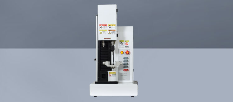
A typical system combines a rotary drive, an axial loading mechanism, a force transducer, a torque transducer, and position feedback. The screw is held through a suitable driver, while the test block is restrained against unwanted movement. Some arrangements measure torque in the rotating drivetrain; others measure reaction torque at the specimen fixture. Either arrangement requires a clear account of which components sit inside the measurement path.
Strain-gauge transducers are commonly used to convert elastic deformation into an electrical signal. Signal-conditioning electronics and calibration coefficients convert that signal into engineering units. The displayed value is therefore the end of a measurement chain, not an independent indication of accuracy. Transducer behavior, mounting, electronics, and software all contribute to the result.
The force and torque channels should share a coordinated time base with rotational position and axial displacement. Otherwise, a torque rise may appear to precede or follow engagement simply because the channels are misaligned. Synchronization becomes especially important when evaluating short engagement transitions rather than steady insertion.
Axial travel is not always penetration depth
Crosshead displacement can include fixture compliance, driver compression, and movement while clearances are taken up. It should not automatically be labeled screw penetration. If penetration is calculated from machine travel, the method needs a defined contact reference and an assessment of compliance. Rotational position provides another useful reference, but converting revolutions into depth assumes the screw is advancing as intended rather than slipping or damaging the material.
Control mode changes the question being answered
Before comparing equipment, establish which variable the procedure controls. Under force-controlled insertion, the machine regulates axial load while the screw rotates, and advancement becomes a response. Under displacement-controlled insertion, the machine prescribes axial motion and measures the resulting force. These approaches can produce different histories even with the same screw and test block.
A prescribed feed that is incompatible with the screw’s natural advancement can impose additional compression or restraint. For a conventional single-start thread advancing normally, nominal travel per revolution corresponds to pitch; for a multi-start thread, lead is the relevant quantity. This relationship is useful for diagnosing the setup, but it does not replace the control requirements of the selected test method.
Force control has its own risks. An aggressively tuned controller may overshoot at initial contact, while a slow response may allow the applied load to fall during engagement. A specification stating “constant axial force” should therefore be supported by recorded force traces, not just a selectable setpoint.
Standards define the method—not just the report heading
ASTM F543, covering metallic medical bone screws, is a relevant starting point when reviewing self-tapping test requirements. Assessors should consult the applicable edition and specific procedure to confirm specimen preparation, loading conditions, rotational settings, endpoint definitions, and reporting requirements. An equipment description that merely references ASTM F543 does not establish that every configuration or software routine satisfies the intended procedure.
ASTM F1839 addresses rigid polyurethane foam used as a standard material for testing orthopedic devices and instruments. Where such material is specified, its relevant properties and identification should be documented. Standardized foam supports controlled mechanical comparisons; it should not be described as reproducing every feature of living bone.
A defensible protocol distinguishes prescribed requirements from internal development choices. If a team changes the pilot hole, insertion speed, or endpoint to investigate a design, the resulting comparison may still be useful. However, those departures should be visible, and the result should not be presented as an unmodified standardized test.
Why alignment and preparation can dominate the result
The driver axis, screw axis, and pilot-hole axis need to be aligned. Angular mismatch introduces bending and side loading, which can affect the sensors and increase friction. A driver that fits poorly may wobble or partially disengage. Neither problem can be corrected reliably by filtering the recorded curve.
Specimen restraint must prevent rotation without creating a different source of variability. Excessive clamping can damage the block, while insufficient support allows movement. The available material around the hole and the spacing between test locations also need to follow the procedure or a justified internal protocol.
Pilot-hole diameter, depth, direction, and preparation method influence engagement. So do material condition and previous damage near the test site. When investigating an unexpected torque increase, checking these factors is often more productive than immediately attributing the change to screw geometry.
Read the curve before accepting the peak
A useful review follows the insertion sequence: initial contact, establishment of thread engagement, and continued advancement through the defined evaluation interval. These stages are not guaranteed to produce clean, separate regions. Nevertheless, viewing torque and force against time, rotation, and validated displacement can reveal behavior that a summary statistic conceals.
- A short torque spike at first contact may reflect engagement impact or drivetrain clearance rather than sustained tapping resistance.
- Rising torque with increasing engagement can reflect accumulating friction, material interaction, or both; it is not automatically evidence of poor cutting geometry.
- A sudden torque drop warrants investigation for stripping, loss of driver engagement, specimen movement, or a material boundary.
- A late peak may come from screw-head seating or reaching the bottom of a hole. It should not silently become the reported tapping peak.
The evaluation window must therefore be defined before comparing designs. State where analysis begins, where it ends, and how excluded events are handled. Preserve raw data alongside processed curves, particularly when smoothing changes peak magnitude or timing.
Equipment specifications that deserve closer scrutiny
Load capacity alone is a weak basis for selecting a bone screw self-tapping performance tester. The expected working loads should fall within a calibrated, usable measurement range. An oversized transducer may offer ample overload capacity while providing inadequate uncertainty or signal quality for low-load engagement measurements. Display resolution is not a substitute for verified measurement performance.
Request calibration information covering the intended force and torque ranges, including applicable directions and traceability. Ask how cross-talk is assessed when axial and torsional loads act together. Separate calibration of each channel does not, by itself, demonstrate that the assembled system is insensitive to combined loading or mounting effects.
Acquisition rate, measurement bandwidth, and filtering should be considered together. High sampling frequency cannot recover a transient already attenuated by the sensor or electronics. Conversely, aggressive smoothing can conceal short events. The supplier should explain what is sampled, what is filtered, what is displayed, and what remains available in exported files.
For acceptance testing, use representative screws and test materials across the intended operating range. Examine load regulation, alignment adjustments, repeatability, stopping behavior, and report reconstruction. A demonstration at one convenient load point provides limited evidence for a broader application.
Build a reviewable test record
The final record should connect screw identification, material batch, hole preparation, fixture arrangement, control settings, calibration status, and analysis rules to the underlying signals. Repeated tests should use independent test locations under documented conditions. This makes it possible to investigate variation rather than merely report it.
Paratronix Instruments Co., Ltd. develops, manufactures, and supplies packaging testing instruments for pharmaceutical packaging, plastics, and high-barrier materials. For a specialist orthopedic test, that stated background should not be treated as proof of bone-screw testing capability. Any proposed solution still needs application-specific evidence covering fixtures, combined-load measurement, control behavior, and the applicable procedure.
The practical next step is to agree on a test protocol before finalizing equipment requirements. Define the controlled variable, expected load range, material preparation, and evaluation window. Then require the system to demonstrate synchronized force, torque, and advancement records under those conditions. That evidence is far more useful than a single peak value or a broad claim of standards compatibility.
Leave A Reply
Search by Keywords