




Recent Posts
 How Bone Screw Self-Tapping Testers Measure Axial Force and Tapping TorqueOct 17, 2026
 ASTM F543 Bone Screw Pull-Out Testing: Setup and Reporting RequirementsOct 17, 2026
 What does a lipstick breaking strength tester actually measure?Oct 16, 2026
 What Does an Adhesive Tack Tester Measure in Pressure-Sensitive Tapes?Oct 15, 2026
 Which gases can a gas transmission rate tester actually measure?Oct 14, 2026

A useful ASTM F543 bone screw pull-out result must connect the measured force to a defined screw, test medium, insertion procedure, and loading arrangement. A peak load without those conditions provides little basis for comparing designs or deciding whether a production lot meets an established requirement. For quality and safety teams, the first question is whether the laboratory can reproduce the conditions behind the result.
ASTM F543 addresses metallic medical bone screws, including axial pull-out testing. Its pull-out method evaluates resistance to extraction under controlled axial loading. It does not, by itself, establish a universal acceptable pull-out force or demonstrate clinical fixation performance. A defensible test program therefore needs both a procedure tied to the applicable standard edition and an acceptance rule appropriate to the product and intended assessment.
Define the test claim before setting up the equipment
Begin by identifying the ASTM F543 edition and the applicable axial pull-out provisions in the laboratory’s controlled procedure. Exact dimensions, preparation conditions, loading parameters, calculations, and mandatory reporting items should come from that edition. A method copied from a previous project or a machine’s software library can carry assumptions that do not fit the screw being evaluated.
The purpose of the test also changes how results should be interpreted. A design comparison needs controlled conditions that allow differences between screws to be assessed. Routine quality control needs a stable method and a justified acceptance criterion. An investigation into a failure may require additional measurements or modified conditions. Where a procedure departs from the standard, the report should identify the departure and explain how it affects the claim of conformity.
Keep the scope of the measurement explicit. Axial pull-out testing assesses one loading condition. It does not establish resistance to every combination of bending, torsion, repeated loading, or biological change encountered after implantation. Similarly, a higher force in a selected test medium does not automatically prove superior clinical performance.
ASTM F543 is a test standard, not a product certification issued when a specimen exceeds a particular force. Any pass/fail statement needs a separately defined requirement, such as an approved product specification or a justified comparison criterion. Establish that requirement before reviewing the results.
Control the screw–medium interface before applying load
Much of the variability in pull-out testing develops during specimen preparation. The material surrounding the threads, the prepared hole, and the engaged thread length all affect the interface that will resist extraction. A precisely calibrated machine cannot compensate for inconsistent preparation.
Test medium and specimen geometry
Use the test medium specified by the applicable method and approved protocol. Record its identity, relevant material specification, lot, dimensions, and any required conditioning. Where synthetic material is used, its grade or density designation should remain traceable to supplier documentation. A description such as “bone substitute” is too broad to support a meaningful comparison.
Block dimensions, screw location, spacing between holes, and distance from edges also require control. Nearby holes or boundaries can alter how the surrounding material carries load. Reusing a block requires an established layout and a basis for deciding which locations remain suitable. An apparently undamaged surface does not demonstrate that the material beneath it is unaffected by an earlier test.
If cadaveric or animal bone is used for a supplementary investigation, document the anatomical source, preparation, storage, and relevant specimen characteristics. Results from biological tissue should be interpreted within that study design. They should not be treated as interchangeable with results from a standardized synthetic medium.
Hole preparation and insertion
Document the pilot-hole dimensions and preparation method, together with tapping or other preparation where applicable. Tool condition and hole direction matter because preparation can change the material engaged by the threads. The procedure should identify how the hole is produced and how preparation equipment is controlled.
Define insertion depth through an unambiguous reference. Overall screw length, penetration depth, and threaded engagement length describe different things, particularly when screws have an unthreaded section or a tapered tip. Record the quantity required by the method and enough supporting information to reconstruct the setup.
Insertion controls should also cover the driver, insertion approach, and any prescribed speed, torque measurement, or seating condition. Avoid adding an uncontrolled final tightening step. If the screw head compresses the block or another component, the resulting setup may introduce effects beyond the intended thread–medium interaction.
For comparisons, hold preparation conditions constant wherever the protocol requires equivalence. If two screw designs require different preparation methods, define those differences in advance. The report should make clear whether the comparison evaluates screw geometry under common conditions or each screw with its intended preparation procedure.
Configure the load path, then verify the measurement
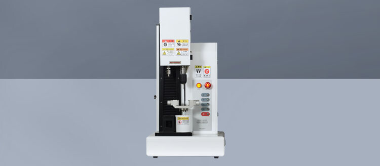
A bone screw pull out force tester needs a suitable tensile loading system, a force transducer with appropriate performance over the working range, controlled motion, and fixtures that maintain the required axial arrangement. The machine’s maximum force rating alone says little about whether it can produce useful data for a particular screw.
Select the force-measurement range using the expected loads and the transducer’s verified capabilities. Resolution, accuracy, calibration coverage, and overload margin all deserve attention. A display with many decimal places does not establish measurement quality. The laboratory should be able to connect the reported force to the instrument identification and its calibration status at the time of testing.
Alignment and fixture support
The extraction force should act along the intended screw axis. Offset gripping, an inclined screw, or an unevenly supported block can introduce bending or other unintended loading. These conditions can alter the force trace and failure mode, even when the software reports a clean peak.
The screw-head attachment must transmit load securely without slipping, damaging the screw prematurely, or imposing an unintended restraint. The block fixture must support the specimen in accordance with the method while providing the required clearance around the extraction region. Fixture geometry deserves the same procedural control as screw insertion.
Before starting a series, check the assembled load path with a representative specimen. Confirm that the connection seats consistently, that the block is stable, and that fixture contact does not interfere with the expected extraction movement. Photographs or a dimensioned fixture drawing can make the arrangement easier to reproduce.
Loading conditions and data acquisition
Use the loading rate and other test conditions required by the applicable standard edition and protocol. Record the actual settings. Terms such as “slow tension” or “standard speed” do not identify a reproducible condition. Any preload, seating operation, force zeroing, and displacement zeroing should follow a defined sequence.
Crosshead movement includes deformation and movement throughout the loaded system. It can contain contributions from the frame, fixtures, connections, and specimen. If displacement at a particular force or at failure will support a decision, identify where displacement is measured and what that measurement represents. Machine travel should not be described as local screw movement without supporting justification.
Data acquisition should resolve the force response adequately, including the region around maximum load and failure. Record relevant acquisition and processing settings, especially when results will be compared across machines or laboratories. Filtering and peak-detection rules can influence the reported maximum. Retain the original data so an unusual trace can be reviewed.
Report enough information to reconstruct and judge the result
The applicable ASTM F543 edition determines the mandatory reporting requirements. A useful quality record also needs enough detail to explain the result, support repeat testing, and distinguish specimen behavior from a setup problem. The following record categories provide a practical review framework; the laboratory should reconcile them with the exact requirements of its controlled method.
- Method and purpose: standard designation and edition, applicable procedure, test objective, approved protocol, and documented deviations.
- Screw identification: specimen identifier, design or part number, lot, relevant dimensions and material information, and condition before testing.
- Test medium: material identity, grade or density designation where applicable, lot, block dimensions, conditioning, and specimen layout.
- Preparation: hole preparation, tools, tapping where applicable, insertion procedure, engagement depth, and relevant seating conditions.
- Equipment and fixtures: machine and force-transducer identification, calibration status, gripping arrangement, block support, and alignment controls.
- Test execution: loading rate, preload and zeroing procedure where used, displacement measurement basis, acquisition settings, and test endpoint.
- Results and observations: individual results, force–displacement records, failure modes, anomalies, excluded tests with reasons, and the basis for any acceptance decision.
Keep individual specimen results available alongside any mean and measure of variation used in the report. A group average can conceal a low result or a mixture of different failure mechanisms. State how many specimens were prepared, how many were tested successfully, and how many contributed to the reported statistics. Select sample size according to the test objective and governing requirements; a convenient specimen count does not establish statistical adequacy.
Distinguish pull-out from an interrupted or invalid test
Review the force trace together with the physical specimen. Thread-related failure in the medium, block splitting, screw fracture, and fixture slippage have different implications. A maximum force can be recorded in all of these situations, but the number alone does not establish that the intended pull-out event was measured.
Define validity and exclusion rules before testing. Fixture slippage may justify repeating a test under an approved rule. A low result from an otherwise valid specimen requires evaluation against the established criterion. Excluding an inconvenient value after seeing the group statistics undermines the comparison.
If the test ends at a travel or machine limit before the specified event occurs, describe the endpoint accurately. The highest recorded force is not automatically a completed pull-out strength measurement. Likewise, a screw fracture should remain visible in the report because it may limit what can be concluded about the surrounding interface.
Make the acceptance decision traceable
For quality release, identify the acceptance criterion, its source, and the decision rule applied. Where a result lies close to a limit, the laboratory’s treatment of measurement uncertainty should be established rather than improvised. For design comparisons, explain the comparison basis and any preparation differences that constrain the conclusion.
A reviewer should be able to follow the final force value back to the specimen, preparation record, fixture arrangement, instrument record, and original trace. When that chain is complete, a change in pull-out performance can be investigated against known conditions. When it is incomplete, even a plausible peak force leaves the quality team without a reliable basis for its next decision.
Leave A Reply
Search by Keywords