




Definition And Industrial Context
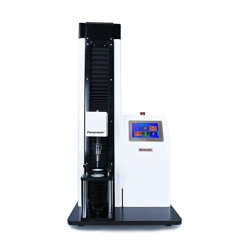
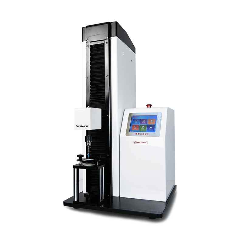
A combination caps puncture force Tester is a force measurement system used to evaluate penetration of an access component within a combination cap or closure assembly. Depending on the package design, the component may include a polymeric membrane or elastomeric element intended to be pierced by a spike or needle. The test records resistance as a defined penetrator travels through the specimen. Results help manufacturers assess whether the closure can be accessed consistently under specified conditions.
Combination caps vary in material, geometry and intended use, so puncture force is not an intrinsic value that can be compared without context. A spike's tip geometry, the location of contact, the support beneath the cap and the rate of travel all influence the result. A meaningful specification identifies the complete assembly and test configuration, rather than relying on a force limit alone. Units are normally reported in newtons, together with the method and specimen condition.
Puncture force is one part of closure performance, not proof of package integrity or clinical suitability. A cap that meets a penetration limit may still require separate assessment of sealing, leakage, compatibility and other application-specific properties. Quality teams use puncture testing during development, incoming inspection, process validation and batch monitoring. The appropriate acceptance criteria should come from product requirements, risk assessment and method validation, not an assumed universal threshold.
Measurement Principles And Tester Types
A typical test begins with a cap secured in a fixture that represents the intended support condition. A probe or representative access device moves toward the puncture site at a controlled speed while a load cell measures force. Software or the operator records force against displacement or time. The maximum force within the defined penetration interval is often the primary result, although the complete curve can reveal initial contact, deformation, breakthrough and subsequent friction.
Motorized single-column and multipurpose force testers can perform puncture testing when equipped with a suitable load cell, fixture and probe. Dedicated configurations may simplify repetitive closure testing, while a multipurpose platform can support other mechanical tests through fixture changes. Selection should be based on the required force range, control of speed and travel, data capture and sample handling. A manual stand may be useful for preliminary observations, but operator-dependent movement can make comparisons less reliable.
Probe selection must reflect the question being asked. A production or representative spike can help assess access performance, while a defined laboratory probe may be appropriate for controlled material comparisons. The two approaches do not necessarily produce interchangeable results. Specify whether probes are new or reused, how their condition is inspected, and when they are replaced. Dullness, damage and residue can change contact mechanics and introduce variability between test runs.
Applications And Standards
Typical users include closure manufacturers, pharmaceutical packaging developers, medical product producers, contract testing laboratories and incoming quality teams. During development, they may compare membrane formulations or cap geometries using a common fixture and probe. In routine production, the same method can help detect shifts associated with raw materials, molding or assembly. Procurement teams can also use agreed test conditions to make supplier data more comparable before approving a component.
Standards must be selected for the material, device and intended claim. ASTM F1306 addresses slow-rate penetration resistance of flexible barrier films and laminates; it should not automatically be treated as a method for a finished combination cap. Relevant pharmacopoeial, packaging or device requirements may also apply depending on the product and market. Confirm the current edition, scope and any regulatory obligations, then document deviations when a product-specific method is necessary.
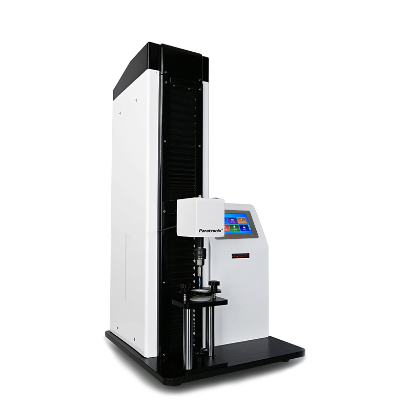
For buyers evaluating a combination caps puncture force Tester, paratronix lists the PMT-C puncture force Tester as a related product and offers a broader range of packaging test equipment, including leak and seal strength testers. Ask the supplier to demonstrate whether the PMT-C can accommodate the actual cap, access device and required method before specifying it. Where seal integrity is a concern, consider a separately justified leak test; puncture force alone cannot establish that a closure remains sealed.
Method Development And Quality Control
Start by defining the purpose of the test and the condition of the sample: loose component, assembled cap or cap fitted to its intended container. Specify conditioning time, temperature and any relevant humidity, as well as sampling locations and the number of specimens. Design the fixture to prevent unintended movement without crushing the closure. Document alignment, contact detection, test speed, penetration depth and the rule used to identify the reported peak.
Before routine use, evaluate the measurement system with representative samples spanning the expected force range. Check load cell calibration and displacement or speed verification according to the instrument manufacturer's instructions and laboratory procedures. Assess repeatability and intermediate precision across operators, days and, where relevant, instruments. Investigate outliers using documented rules rather than removing unfavorable results. Establish acceptance limits using development evidence, process capability and the risk associated with the intended application.
A controlled record should identify the specimen lot, fixture, probe, instrument, software or method version, environmental conditions and calibration status. Retain individual results and force curves where useful, especially when investigating a change in failure behavior. If the fixture, probe supplier or test speed changes, assess whether the method remains comparable and whether revalidation is needed. Train operators to recognize misalignment, incomplete penetration and specimen movement, and define when a test must be repeated.
Equipment Selection And Ownership Costs
Begin equipment selection with representative samples and a written method requirement. Ask for the anticipated force range, usable load cell range, accuracy specification, available speeds, travel and data acquisition capability to be confirmed against the application. Check whether the fixture can hold the complete closure securely and whether the probe can be aligned and replaced consistently. A supplier demonstration using real samples is more informative than selecting solely from a catalog specification.
Total ownership cost includes the instrument, application-specific fixtures and probes, installation, training, calibration, preventive maintenance and replacement parts. Software licensing, data export, qualification documentation and service response may also affect the budget. Consider sample throughput and changeover time when comparing platforms. A multipurpose tester can spread equipment cost across methods, but fixture changes and scheduling may reduce that benefit if several departments need simultaneous access.
Estimate return on investment using a realistic baseline: current test time, external laboratory expense, investigation workload and the consequences of delayed release. Compare these with annual operating costs and the useful life assumed by the buyer. Include the cost of method development and validation, because an instrument does not make a method suitable by itself. Request a written quotation defining included accessories, service scope, delivery terms and exclusions before comparing supplier offers.
Maintenance And Future Trends
Routine care focuses on clean fixtures, undamaged probes, secure connections and the condition of the load cell and moving assembly. Set calibration and maintenance intervals through laboratory procedures, instrument instructions, usage and observed stability; there is no single interval suitable for every site. Perform documented checks after transport, repair or an overload event. Keep spare probes and critical fixture parts available when production release depends on the test.
Packaging laboratories are increasingly interested in traceable electronic records, easier data transfer and greater consistency between operators and sites. Automation and digital force curves can support these goals, but their value depends on validated configurations and controlled data handling. As closure materials and access devices evolve, existing test limits may need review. Correlation between laboratory measurements and intended-use performance remains an important development task, especially when probe geometry changes.
For a practical next step, prepare a sample package, drawing or access device and a draft test procedure for discussion with paratronix. Include expected forces, test speed, penetration depth, throughput, reporting needs and any applicable standard or internal specification. Ask which fixture and load cell are proposed, what evidence supports the configuration and what training and service are available. Confirm all technical capabilities in the final quotation and acceptance documentation.
 Building an ASTM-Aligned Plastic Film Puncture Test Method for Incoming QCPlastic films puncture force Tester guidance for building an ASTM-aligned incoming QC method with controlled conditions, reliable limits, and defensible film release decisions.
 Rubber Stopper Puncture Force Testing for Reliable Vial Closure Quality ControlRubber stoppers puncture force Tester solutions help verify vial closure performance, improve test repeatability, and support reliable injectable packaging quality control.
 When ASTM F1306 is suitable for laminated film puncture testingLaminated films puncture force Tester insights: learn when ASTM F1306 delivers reliable puncture resistance data, better laminate comparisons, and confident material specifications.
Search by Keywords