




Recent Posts
 Rubber Stopper Puncture Force Testing for Reliable Vial Closure Quality ControlSep 15, 2026
 Building an ASTM-Aligned Plastic Film Puncture Test Method for Incoming QCSep 15, 2026
 7 Critical Parameters to Evaluate When Selecting a Syringe Needle Tester for ISO 7886 ComplianceSep 14, 2026
 Can an infrared method water vapor permeability tester replace gravimetric testing for ISO 15106-3 compliance?Sep 14, 2026
 Comparing Gravimetric, Coulometric, and Modulated IR WVTR TestersSep 11, 2026
Start With the Failure You Need Incoming QC to Catch
An ASTM-aligned puncture method is worth building when puncture resistance is a meaningful part of packaging performance: a film may be exposed to sharp product edges, handling damage, pallet contact, medical-device components, corners of secondary packs, or concentrated stress during forming and filling. In these cases, incoming QC needs more than a supplier certificate or a nominal film thickness. It needs a repeatable way to identify lots that are materially weaker than the film approved for the application.
The method should begin with a practical question: what type of puncture event is the material expected to resist? A slow probe penetrating a flat specimen does not reproduce every distribution or production hazard. It can, however, provide a controlled comparison between incoming lots when the same probe, support fixture, rate, conditioning process, and calculation rules are used consistently.
For flexible barrier films and laminates, ASTM F1306 is often the relevant starting point because it addresses slow-rate penetration resistance. It should not be treated as a generic label for every film puncture test. Stretch wrap, geomembranes, rigid sheets, and highly elastic materials may fall under different test approaches or require a method tailored to their actual service condition. Calling a method “ASTM-aligned” is appropriate when the laboratory has selected a relevant ASTM framework, followed its applicable principles, and documented any justified deviations. It does not mean that any force-versus-displacement test automatically represents ASTM compliance.
Choose the Standard Framework Before Setting a Pass/Fail Limit
A common incoming-QC mistake is to begin with a force limit because it is easy to communicate: “the film must withstand X newtons.” That limit has little value unless the test configuration behind it is stable. Puncture force is affected by probe shape, specimen support geometry, test speed, film orientation, laminate construction, conditioning history, and the way the maximum force is identified from the curve.
ASTM F1306 provides a useful structure for defining those conditions in a slow-rate penetration test. The laboratory should review the current controlled copy of the standard and confirm that the material and intended test objective fit its scope. Where the actual packaging hazard differs from the standard configuration, the method can still use ASTM principles while explicitly identifying the variation. For example, a package exposed to a narrow product corner may require a probe shape that better represents that corner than a general-purpose rounded probe.
The distinction matters for supplier discussions. A report stating only “puncture resistance: pass” leaves too much open to interpretation. A report that identifies the governing method, probe geometry, support fixture, speed, sample conditioning, number of specimens, and reported values can be repeated by another laboratory and investigated when results diverge.
Before releasing the method, define the intended quality decision in one sentence. Examples include:
- Reject incoming film lots that show insufficient resistance to concentrated penetration during package handling.
- Monitor lot-to-lot consistency against an approved film construction.
- Assess whether a supplier material change has altered puncture performance.
- Investigate puncture-related failures without confusing them with seal-strength, tear, or impact failures.
That final point is important. A puncture test does not replace seal testing, dart impact testing, tensile testing, coefficient-of-friction testing, or visual inspection. It should be used when its failure mode has a credible connection to the risk being controlled.
Build the Method Around Controlled Test Conditions
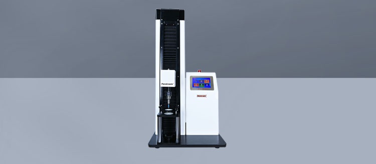
A plastic films puncture force Tester can generate a force-displacement curve quickly. The difficult part is ensuring that the curve means the same thing from one incoming inspection cycle to the next. The work instruction should define every condition that can change the result enough to affect a release decision.
Specimen identity and sampling
Record the supplier, material code, lot number, nominal structure, thickness specification, and roll or sheet location. Sampling from only the roll edge or only the first accessible layers can conceal variation caused by winding, gauge profile, coating application, or conversion conditions. The sampling plan should state how many rolls are selected, where specimens are taken from each roll, and how many valid replicates are required.
Machine direction and transverse direction should be marked where orientation may affect performance. Some films and laminates show different deformation and failure behavior by direction. If the intended package loading has a dominant orientation, that orientation should be tested deliberately rather than mixed into a single unqualified average.
Conditioning and specimen handling
Plastic films are sensitive to storage temperature, humidity, relaxation after unwinding, and handling damage. A roll transferred directly from a cold warehouse, a sample cut from material under tension, or a specimen touched repeatedly near the test area can introduce unnecessary variation.
The written method should identify the conditioning environment and duration used before testing, consistent with the selected standard and the material's needs. It should also specify how specimens are cut, how they are protected from creasing and contamination, and which defects make a specimen invalid. If a specimen slips in the fixture or has a visible crease in the test zone, the result should not simply be included because it exists; the event and reason for invalidation should be documented.
Probe, support fixture, and speed
Probe geometry is not a minor equipment detail. A rounded probe distributes stress differently from a pointed or conical probe. A larger diameter may emphasize film stretching before rupture, while a smaller contact area may make local defects and thin spots more influential. Support aperture size and clamping condition also determine how freely the film can deform before penetration.
For this reason, a probe should not be changed merely because another laboratory uses a different one. Once a configuration has been linked to an approved film and packaging risk, changing the probe, support aperture, or test speed creates a new test condition. The historical acceptance limit may no longer apply.
Test speed deserves the same discipline. Film polymers and adhesive layers can respond differently when loaded at different rates. A faster crosshead may produce a higher apparent peak force for some materials, but that does not automatically make the material better. The selected speed should reflect the relevant ASTM method or a documented rationale related to the expected hazard, then remain fixed for routine incoming inspection.
Instrument capability and data capture
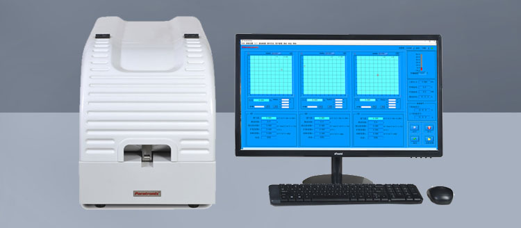
The tester should be appropriate for the expected force range. A load cell with an excessively large capacity can reduce useful resolution at low forces, while one that is too close to the expected maximum may be overloaded during an abnormal test. The system should also capture force and displacement at a rate sufficient to identify the puncture event rather than merely displaying a final number.
Routine checks should cover load indication, displacement or crosshead movement, probe condition, fixture alignment, and software settings. A damaged probe tip, loose fixture, or altered test template can change results before an operator sees an obvious fault. Calibration alone does not demonstrate that the full test setup remains fit for use; verification of the assembled test system is also needed.
Use More Than Peak Force When the Failure Mode Requires It
Peak puncture force is the most familiar output, and it is often useful for incoming screening. Yet it describes only the highest load reached during the event. Two films can show a similar peak force while behaving differently before rupture: one may stretch substantially and absorb more energy, while another may fail abruptly after limited deformation.
Where the product risk involves sustained deformation before puncture, the method should consider whether displacement at maximum force and energy to puncture add useful information. Energy is typically derived from the area under the force-displacement curve up to the defined puncture point. Its calculation must be controlled carefully. The laboratory should define whether puncture is identified by the peak force, an abrupt force drop, visible breakthrough, or another criterion permitted by the selected method.
For multilayer films, retaining representative failed specimens can be especially helpful during an investigation. A drop in peak force accompanied by visible layer separation may point toward a different issue than a clean rupture through an otherwise uniform structure. The test alone may not identify root cause, but it can direct follow-up work toward film gauge, laminate adhesion, resin formulation, coating, orientation, or conversion conditions.
Set Acceptance Criteria From Capability and Packaging Risk
An incoming inspection limit should be based on evidence from the approved material and the package application, not copied from an unrelated data sheet. The starting dataset should include multiple conforming lots tested under the finalized method. This establishes the normal distribution of results for the actual approved construction, rather than an assumed value based only on nominal thickness or generic material type.
Acceptance criteria also need a clear unit of decision. The laboratory may use an individual minimum, a lot average, a lower statistical threshold, or a combination of these. Each approach controls a different risk. An average-only rule can allow one severely weak specimen to be hidden within otherwise high values. An individual-minimum rule may be more sensitive to isolated defects but can generate avoidable holds if sample handling or test repeatability is poor.
A practical release rule often includes both an individual-result condition and a lot-level condition, provided each has been justified with enough baseline data. The rule should also state what happens when results are close to the limit. Retesting should not be an informal route to replace an unfavorable outcome. Define in advance whether confirmation testing is allowed, how many new specimens are required, and when the lot must be placed on hold for engineering or supplier review.
Thickness should be recorded when it is relevant to the specification, but it should not be used casually to normalize puncture results. A thicker film may still perform poorly because of structural defects, poor interlayer bonding, or changes in polymer behavior. Conversely, a thinner but well-engineered structure may show strong puncture performance under the chosen method. Thickness and puncture force answer related, but different, quality questions.
Make the Report Useful for an Investigation
An incoming QC report should allow a later reviewer to reconstruct the test without relying on operator memory. At minimum, it should include material identification, lot traceability, test date, conditioning status, method revision, instrument identification, load cell range, probe and fixture identification, test speed, specimen orientation, number of valid and invalid tests, individual results, summary statistics, and the pass, hold, or fail decision.
The report should also preserve the force-displacement curves when the system supports them. A single reported maximum can hide slippage, multiple rupture events, unusual deformation, or an early force drop. Curves are particularly valuable when a supplier changes resin, adhesive, coating weight, or film construction while nominal specifications remain unchanged.
For safety and quality teams, the aim is not to make the incoming test as complex as possible. It is to make the decision defensible. A method aligned to the applicable ASTM framework, tied to a defined package hazard, and kept under configuration control provides a far stronger basis for release than a standalone force number. Once that foundation is in place, puncture testing becomes a reliable incoming-QC control rather than a periodic comparison exercise with uncertain meaning.
Leave A Reply
Search by Keywords