




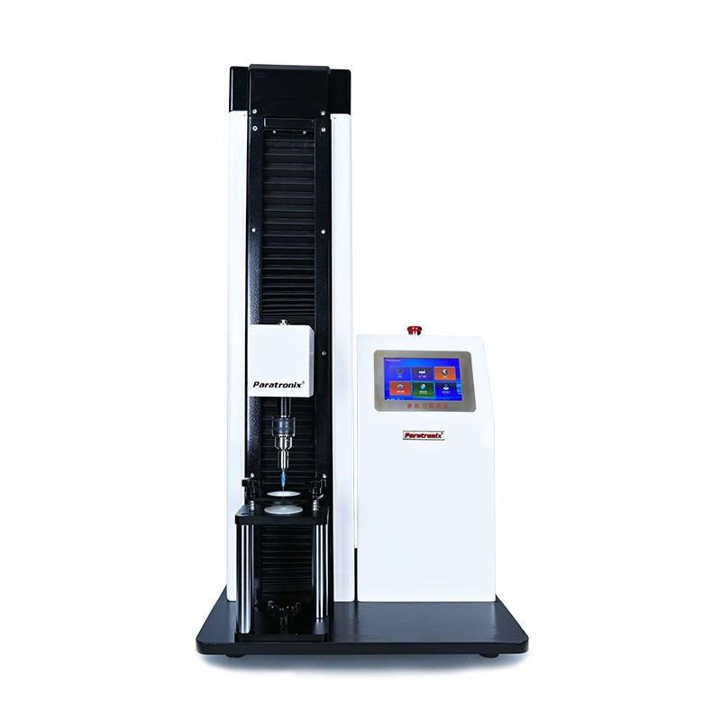
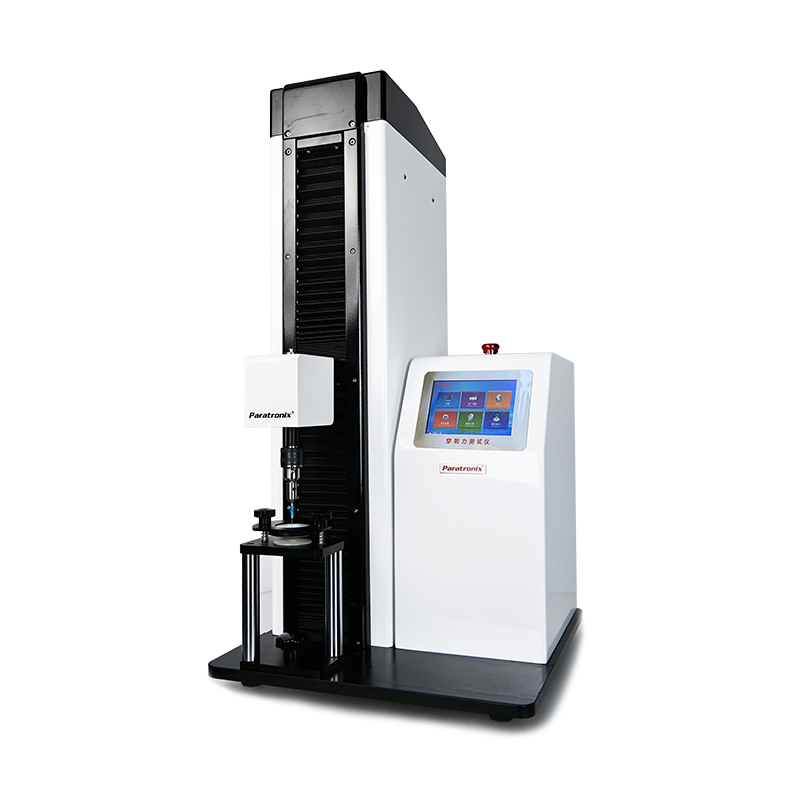
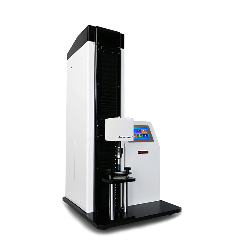
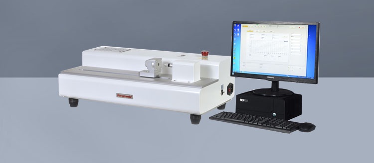
What Is A Puncture Force Tester?
A puncture force Tester measures the resistance of a specimen as a probe advances into and potentially through it. A motorized test system typically moves the probe or specimen at a defined speed while a load cell records force against displacement. The resulting data helps manufacturers compare materials, monitor production consistency, and investigate changes in packaging components.
Peak puncture force is the highest force recorded within the specified test region. Depending on the method, the force at initial penetration, displacement at peak force, or energy calculated from the area under a force-displacement curve may also be useful. These results describe different behaviors, so a report should identify the endpoint rather than simply state a puncture value.
The specimen and its intended use determine the meaning of the result. A flexible film may stretch considerably before rupture, while a rubber stopper can show several force changes as a needle enters and passes through it. A higher peak force is not automatically better: excessive penetration force may create handling problems or compromise a device's intended operation.
Puncture resistance is related to, but distinct from, tensile strength, tear resistance, seal strength, and leak integrity. Each property responds to a different loading or inspection condition. A puncture force test therefore belongs in a broader quality program, with complementary methods selected according to the component, failure mode, and applicable product requirements.
How The Test Principle And Equipment Work
The essential system comprises a force sensor, a controlled drive, a probe, a specimen fixture, and software or a display for recording results. Before testing, the operator mounts the sample, establishes the probe position, and zeros the force reading according to the procedure. The drive then advances at the prescribed speed while the instrument captures the force response.
Probe geometry is critical. A rounded tip distributes contact differently from a sharp needle, and changes in tip diameter, surface condition, or penetration depth can alter the result. Fixtures also matter: aperture size, clamping pressure, and sample support influence how a specimen stretches or moves. Comparisons are meaningful only when these conditions are controlled.
Force-displacement curves can reveal behavior that a single peak value hides. A gradual rise may indicate stretching or compression, while a sudden drop can signal rupture or penetration. Multiple peaks may reflect successive material layers or friction along the probe. Interpretation should be checked against the actual specimen and test method, rather than inferred from curve shape alone.
Load cell capacity and resolution should suit the expected force range. An oversized sensor may limit useful resolution at low forces, while an undersized sensor can be overloaded. Confirm the instrument's specified accuracy across the intended operating range, along with speed control, travel, data acquisition, and compatible fixtures before committing to a configuration.
Main Tester Types And Test Methods
Dedicated puncture systems are configured around a defined test task and may simplify routine operation. A multipurpose mechanical tester can accept interchangeable load cells, probes, and fixtures for puncture and other physical tests. The choice depends on sample throughput, required methods, available laboratory space, and the time needed to change fixtures and verify settings.
Film and flexible packaging tests commonly use a probe and a fixture that supports the specimen around an opening. For stretch wrap, ASTM D5748 describes a puncture resistance procedure; its scope and specified conditions should be checked before use. Other films, laminates, or end uses may require a different published method or a documented internal procedure.
Needle penetration tests use a specified needle or similar probe to examine components such as elastomeric closures. ISO 7864 addresses sterile hypodermic needles and includes penetration-related requirements and methods within its scope; it should not be assumed to define every stopper puncture test. For a closure, establish the applicable product requirements and a suitable method for the intended needle and use.
Puncture and impact tests should also be distinguished. A controlled probe test measures a force response under its specified motion, whereas falling-dart impact methods assess behavior under a different loading condition. ASTM D1709, for example, addresses impact resistance of plastic film by a free-falling dart. Results from these methods are not interchangeable.
Applications, Standards, And Buyer Requirements
Packaging converters and brand owners use puncture testing to compare film structures, investigate material changes, and monitor incoming rolls. Procurement teams can establish acceptance limits with suppliers after agreeing on specimen preparation and test conditions. Testing across representative batches is especially useful when evaluating a new resin, laminate design, or production line setting.
Pharmaceutical and medical packaging teams may assess the force required to penetrate rubber stoppers, caps, or related components. The probe must represent the intended interaction closely enough for the decision being made, including needle dimensions and test speed. Penetration force alone does not establish sterility, container closure integrity, or suitability for a medical application.
Method selection should begin with the destination market, product specification, and current edition of any referenced standard. Where no published method directly matches the application, a documented internal method can define equipment, conditioning, sampling, calculation, and acceptance criteria. Laboratories should also consider applicable customer agreements and regulatory expectations; an instrument purchase alone does not establish compliance.
For buyers comparing equipment, paratronix lists the PMT-C puncture force Tester as a relevant product and offers testing equipment across packaging properties, including leak, seal strength, and permeability testing. Request the PMT-C's current specifications and suitable fixtures for the intended method, then confirm whether its force range, travel, software, and accessories support the samples to be tested.
How To Select And Qualify A Tester
Start with a written application brief covering material, thickness or component dimensions, expected force range, required test speed, penetration depth, and sample volume. Attach the intended standard or internal procedure and identify the results needed for release decisions. Sharing representative specimens with prospective suppliers can help establish whether the proposed configuration can perform the actual test.
Evaluate probe and fixture availability before comparing headline specifications. Confirm that the fixture holds the sample consistently, allows correct alignment, and provides the required support geometry. For needles or other replaceable probes, define how dimensions, wear, and replacement frequency will be controlled. Ask whether additional tooling is needed for each component size.
Review force accuracy, calibrated range, speed accuracy, displacement measurement, and data capture against the method's requirements. Ask for calibration documentation, traceability details, installation requirements, operator training, software capabilities, and local service arrangements. If electronic records are used in a regulated workflow, assess access controls and record handling against the organization's specific requirements.
Before routine use, qualify the complete method with representative samples and trained operators. Check repeatability across specimens, operators, and relevant fixtures; investigate unexpected variation before setting limits. Agreement between laboratories may require an additional comparison using common samples and a shared procedure. Base acceptance criteria on product performance and process knowledge, not an equipment demonstration alone.
Test Workflow, Quality Control, And Maintenance
A practical workflow starts with sampling and conditioning as defined in the method. Record the material lot, sample orientation, thickness where relevant, environmental conditions, and preparation details. Inspect specimens for damage unrelated to the test. Randomize or distribute sampling across a roll or batch when the objective is to assess production variation.
Install the specified probe and fixture, verify alignment, and enter the prescribed speed, travel, and endpoint settings. Zero the force signal at the appropriate stage and secure the specimen consistently. Run the required number of specimens, inspect each curve and failure location, and document invalid tests with their reasons according to the procedure.
A useful report identifies the method version, equipment and sensor, probe geometry, fixture, sample identification, conditioning, test settings, individual results, and any deviations. Summaries such as mean and variability should reflect the sampling plan. Retaining curves and raw data where practical supports investigations when a result shifts or a supplier changes material.
Maintain the tester under the manufacturer's instructions and the laboratory's quality system. Inspect probes and fixtures for wear, contamination, and damage; clean them using materials compatible with the equipment. Establish calibration and verification intervals from risk, usage, and stability, and repeat relevant checks after repair, relocation, or changes that could affect measurement.
Ownership Costs, Return On Investment, And Future Trends
Total ownership cost includes the instrument, suitable load cells, probes, fixtures, software, installation, training, calibration, maintenance, and replacement parts. Budget for sample preparation and operator time as well as any qualification work. A lower initial price may be offset by additional tooling or service costs, so compare quotations using the same application and operating period.
Estimate potential return by comparing current testing and quality costs with a realistic proposed workflow. Relevant factors may include outsourced testing fees, sample turnaround, operator hours, and the cost of investigating unsuitable material. Use actual production data where available, and distinguish measurable savings from benefits such as faster decisions that are harder to price reliably.
Digital recordkeeping and automated data review are becoming more relevant as laboratories manage larger test volumes and supplier datasets. Recyclable or downgauged packaging structures can also require method review when deformation and puncture behavior change. These trends make consistent fixtures, traceable settings, and accessible raw data useful considerations when planning future equipment needs.
To evaluate a puncture force Tester for a specific application, provide paratronix with the sample description, expected force range, test method, required output, and anticipated throughput. Ask for a written configuration and quotation covering fixtures, calibration, training, and service. Compare the proposal with representative test results and your documented acceptance criteria before purchasing.
 Building an ASTM-Aligned Plastic Film Puncture Test Method for Incoming QCPlastic films puncture force Tester guidance for building an ASTM-aligned incoming QC method with controlled conditions, reliable limits, and defensible film release decisions.
 Rubber Stopper Puncture Force Testing for Reliable Vial Closure Quality ControlRubber stoppers puncture force Tester solutions help verify vial closure performance, improve test repeatability, and support reliable injectable packaging quality control.
 How puncture force testing helps control oral liquid cap consistencyOral liquid caps puncture force Tester solutions help verify cap consistency, detect variability early, and strengthen pharmaceutical packaging quality control.
 What does an oral liquid cap puncture force tester measure?Oral liquid caps puncture force Tester measures controlled opening force, breakthrough behavior, and consistency for reliable package quality.
Search by Keywords