




Understanding Luer Taper Testing And Slip Wire Terminology
A Luer Taper resistance to slip wire Tester is a commercial search term for equipment used to evaluate the mechanical security of Luer connections. The phrase needs clarification because medical connector standards distinguish several failure modes rather than grouping them under slip wire resistance. For a Luer lock connector, the intended evaluation may concern resistance to overriding, where locking features ride past one another under tightening torque, or resistance to separation or unscrewing under specified mechanical loading.
Luer connectors use mating conical surfaces with a nominal six percent taper. Luer slip connections rely primarily on engagement between those surfaces, while Luer lock connections add locking features that help retain the assembly. Their behavior depends on geometry, material properties, surface condition, and assembly history. A mechanically secure locking feature does not by itself establish leak tightness, and a leak-tight connection does not establish adequate resistance to unintended disconnection.
Before requesting a quotation, translate the search term into a defined test objective. Identify whether the specimen is a slip or lock design, which connector component is being assessed, and which loading direction represents the concern. This prevents procurement of equipment that measures peak torque but cannot execute the required loading sequence. It also gives design engineers, quality teams, and suppliers a shared basis for discussing fixtures, acceptance criteria, and report content.
Interpreting ISO 80369-7 Requirements And Related Methods
ISO 80369-7 addresses small-bore connectors for intravascular or hypodermic applications. Its requirements cover connector dimensions and functional performance relevant to these applications. ISO 80369-20 provides common test methods used within the connector standards framework. A verification plan should identify the applicable editions, amendments, connector configuration, and referenced procedures before equipment settings are approved. Older documentation referring to ISO 594 requires careful review against the standards applicable to the current product and market.
Relevant performance evaluations can include leakage, stress cracking, resistance to separation, resistance to unscrewing, and resistance to overriding, depending on the connection type and applicable requirements. These evaluations address different mechanisms and should remain distinct in protocols and reports. Exact assembly loads, applied torques, exposure conditions, hold periods, and acceptance limits must come from the applicable controlled standard. A generic torque setting or an instrument supplier's default recipe cannot establish conformity by itself.
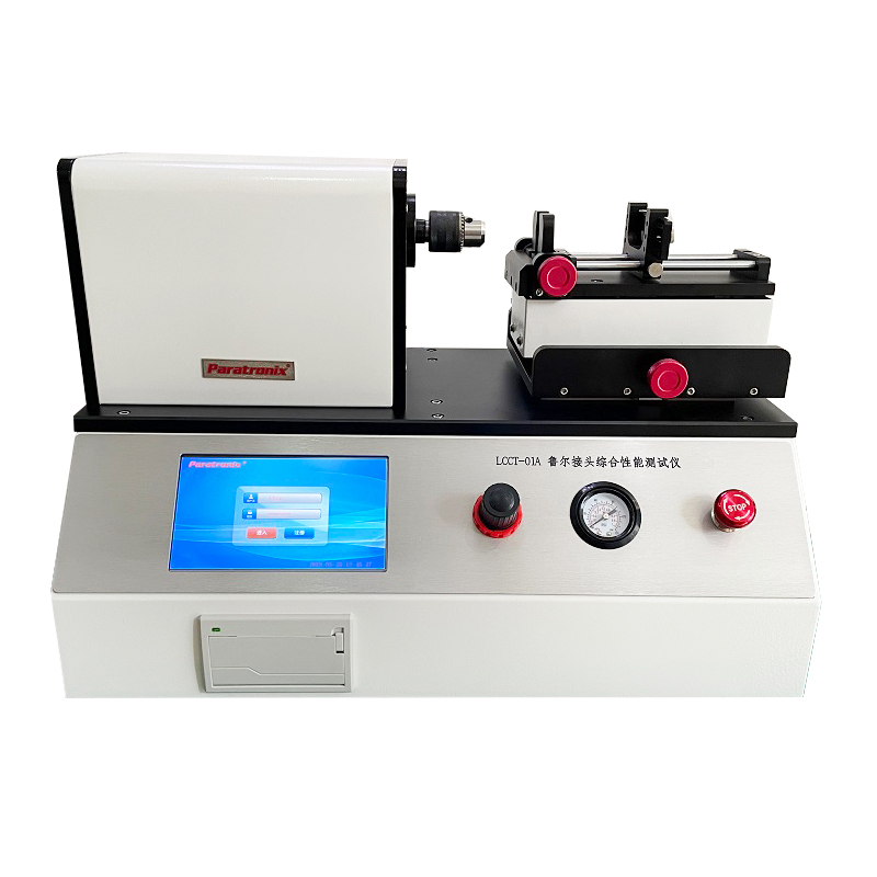
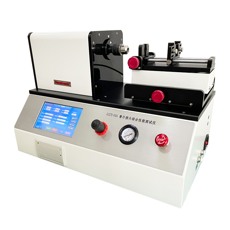
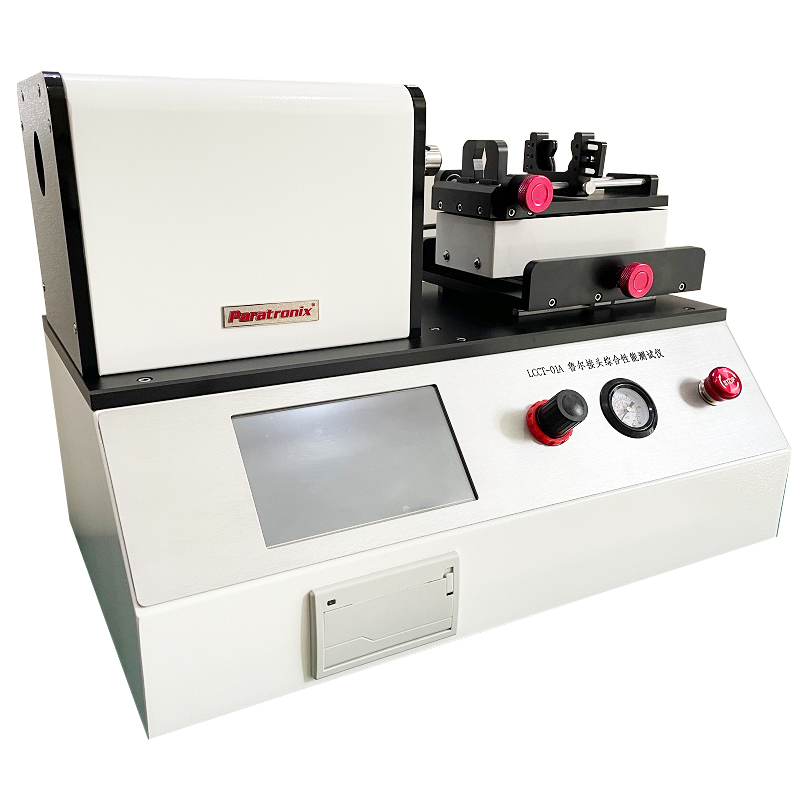
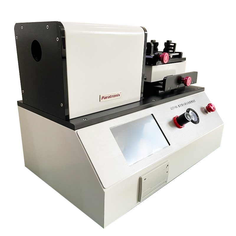
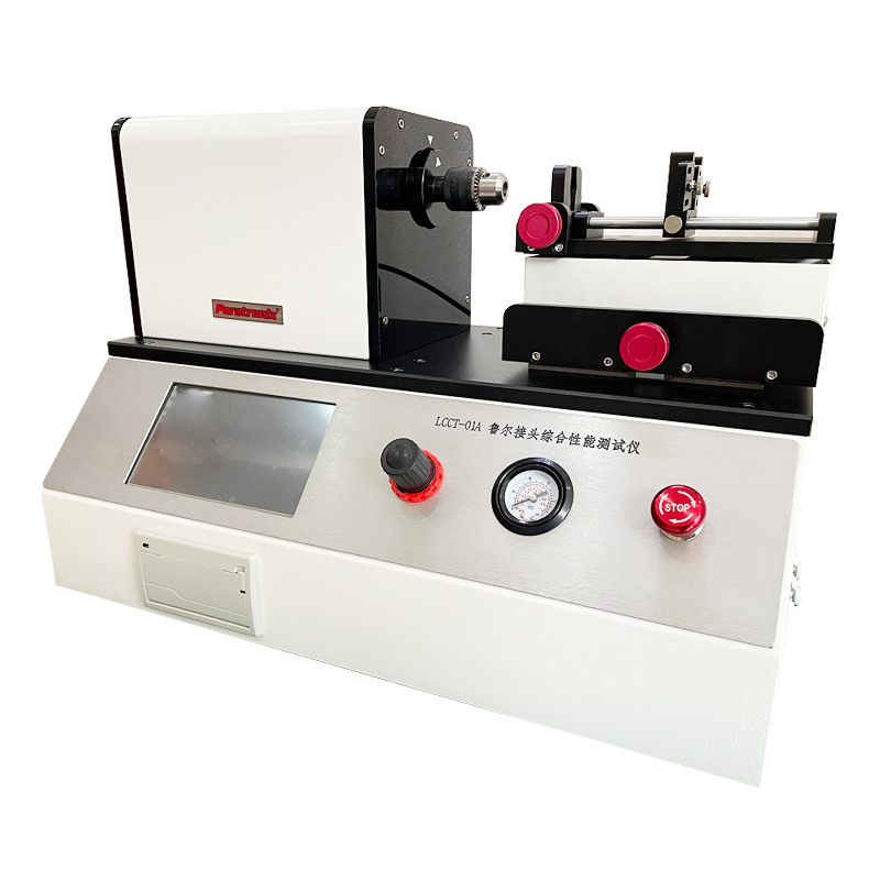
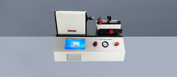
For laboratories considering paratronix, the LCCT-01A Luer Taper Comprehensive Performance Tester is a relevant product to evaluate against this test matrix. Request written confirmation of the supported methods, fixture configurations, measurement ranges, and reporting functions for the supplied configuration. The broader paratronix portfolio includes torque, leakage, and multipurpose testing equipment, which may support complementary laboratory needs. However, portfolio breadth and a model name do not demonstrate that a particular instrument configuration meets every requirement.
Explaining Test Principles And Equipment Categories
Mechanical connector testing applies controlled axial force, rotational torque, or a prescribed combination to a defined assembly. The instrument must hold the specimen without introducing unintended deformation and align its loading axis with the connector. Depending on the method, the system records applied load, torque, displacement, rotation, elapsed time, or the observed connection outcome. Meaningful results depend on reproducing the specified boundary conditions as closely as on selecting sensors with suitable accuracy.
An overriding evaluation challenges the locking engagement under the prescribed tightening conditions. An unscrewing evaluation assesses resistance to loosening under the applicable procedure, while an axial separation evaluation challenges retention along the connection axis. These distinctions matter because identical specimens can respond differently to each loading mode. When a supplier describes slip resistance, ask which physical event the instrument detects and whether its result represents a standard-defined endpoint or an additional engineering measurement.
Equipment commonly falls into manual torque arrangements, motorized torque systems, and integrated platforms combining axial and rotational control. Manual arrangements can support exploratory work when their limitations are understood. Motorized systems improve control of loading and recording, while integrated platforms may simplify methods requiring coordinated actions. A Luer Taper resistance to slip wire Tester should be selected by its demonstrated control and measurement functions. Automation alone does not compensate for unsuitable fixtures, incorrect reference connectors, or an incomplete protocol.
Building A Practical And Traceable Test Workflow
Begin with an approved protocol defining specimen identity, sampling rationale, applicable methods, conditioning, assembly sequence, and acceptance criteria. Include manufacturing variables that could affect performance, such as material grade, mold cavity, sterilization exposure, and aging condition where relevant. Use prescribed reference connectors when required and maintain their identification and inspection records. Testing only against an arbitrary commercial mating component can obscure whether the specimen satisfies the intended interface requirements and may limit comparability between laboratories.
Before loading specimens, confirm calibration status and perform the instrument checks specified by the laboratory procedure and equipment manufacturer. Install the correct fixtures, verify alignment, and establish suitable zero settings. Apply conditioning and assembly loads in the required order, then execute the selected mechanical challenge. Avoid reusing a previously challenged specimen unless the method permits it, because prior tightening, deformation, or stress exposure can alter the result and compromise interpretation of subsequent measurements.
Record specimen identification, equipment identification, reference connector details, environmental conditions when relevant, programmed settings, observed outcomes, and deviations. Where available, retain force or torque traces alongside the acceptance decision. Unexpected behavior should trigger examination of both the specimen and the test setup before a conclusion is assigned. Related investigations into stress cracking can help explain delayed damage, but they require their own defined conditions and cannot be replaced by a short mechanical retention test.
Selecting Equipment For Engineering And Quality Applications
Typical users include medical device manufacturers, connector suppliers, development laboratories, and independent testing organizations. Engineering teams use mechanical testing to compare locking designs and investigate manufacturing variation. Quality teams apply approved methods during qualification, change assessment, or justified routine inspection. Testing after material, tooling, sterilization, or supplier changes can support risk-based verification planning. The extent of retesting should follow the documented impact assessment rather than an assumption that every change requires an identical test package.
Compare instruments using the required working range, measurement uncertainty, control stability, loading capability, fixture accessibility, and specimen compatibility. Resolution is only the smallest displayed increment; it is not proof of measurement accuracy. Ask how performance is verified near the actual operating points and whether calibration covers the relevant force and torque directions. For small connectors, fixture compliance and unintended bending may influence results enough to deserve explicit attention during equipment evaluation and method transfer.
Request a demonstration using representative specimens and a mutually agreed protocol when assessing the LCCT-01A from paratronix. Review the resulting report and any available raw data before finalizing the specification. The supplied business registration identifier, Unified Social Credit Code 91370105689842696E, can support supplier identity checks; it is not evidence of instrument certification or laboratory accreditation. Procurement should separately verify service arrangements, documentation quality, calibration provisions, and the capabilities included in the commercial quotation.
Assessing Ownership Costs And Purchasing Value
The purchase price of a Luer Taper resistance to slip wire Tester is only one component of laboratory cost. Budget for fixtures, reference connectors, installation, training, calibration, maintenance, software options, and replacement parts. Include the engineering time required to establish methods and approve reports. If several connector configurations are planned, confirm whether each requires additional tooling or software. A quotation with limited accessories may appear economical while leaving essential method capabilities outside the initial purchase.
Evaluate productivity using a complete test cycle, including specimen identification, conditioning where applicable, mounting, assembly, loading, inspection, and reporting. The shortest programmed loading step does not necessarily determine daily throughput. Controlled recipes and structured data export may reduce transcription and setup work if the selected system supports them. Estimate savings from measured laboratory activities and expected test volumes, while accounting for training and verification effort. Avoid assigning financial benefits to unverified assumptions about defect reduction.
A purchasing comparison should separate essential capabilities from convenient additions and identify the cost of future expansion. Consider whether local service, spare fixture availability, and calibration turnaround match production needs. Where outsourcing remains practical, compare internal ownership costs with external testing fees, transport time, scheduling constraints, and confidentiality requirements. The strongest investment case connects the equipment specification to a documented workload and a realistic verification plan, with clear responsibilities for operation, maintenance, and technical review.
Planning Maintenance And Future Testing Capabilities
Maintenance intervals should reflect the manufacturer's instructions, usage intensity, laboratory risk assessment, and observed equipment stability. Inspect grips, alignment components, and reference connectors for damage or wear that could affect loading. Check performance after repairs, relocation, overload events, or other changes that may influence measurement. Calibration intervals should be justified and reviewed using historical results. A fixed calendar interval without attention to actual use may overlook deterioration or impose unnecessary downtime on lightly used equipment.
Future equipment development is likely to emphasize coordinated force and torque control, improved traceability, configurable reporting, and easier integration with laboratory information systems. Demand for electronic records also makes access control, method version management, and reliable data export relevant purchasing considerations. These features support consistent work when implemented and verified appropriately. They do not replace competent operators, suitable reference components, or technical review, and buyers should confirm which functions are available rather than assume them from automation claims.
To prepare an actionable inquiry for paratronix, provide connector drawings or interface details, sample materials, intended methods, expected workload, and reporting requirements. Ask for an LCCT-01A configuration proposal linking each requested test to its fixtures, measurement capabilities, and supporting documentation. This gives both parties a concrete basis for assessing suitability and identifying any gaps before purchase. The resulting decision should support repeatable measurements and defensible product verification while keeping the scope of each test clearly defined.
 What Does a Luer Taper Stress Cracking Tester Reveal About Connector Integrity?Discover how a Luer Taper Stress Cracking Tester reveals connector weaknesses under defined conditions. Explore key testing insights for smarter material and equipment choices.
 ISO 80369-7: Planning Stress Cracking Tests for Luer ConnectorsLuer Taper stress cracking Tester guide: plan ISO 80369-7 tests with controlled assembly, conditioning, and clear acceptance criteria. Discover how to select equipment for reliable results.
 Axial Load, Torque, and Hold Time in Luer Connector Stress Cracking TestsLuer Taper stress cracking Tester selection starts with axial load, torque, and hold time control. Discover essential checks for repeatable testing and smarter equipment decisions.
Search by Keywords