




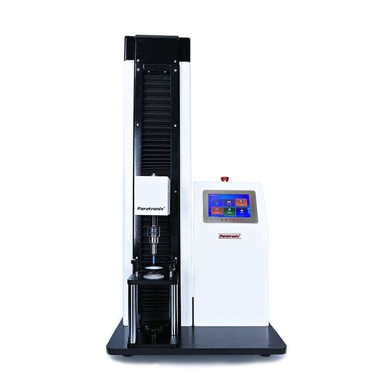
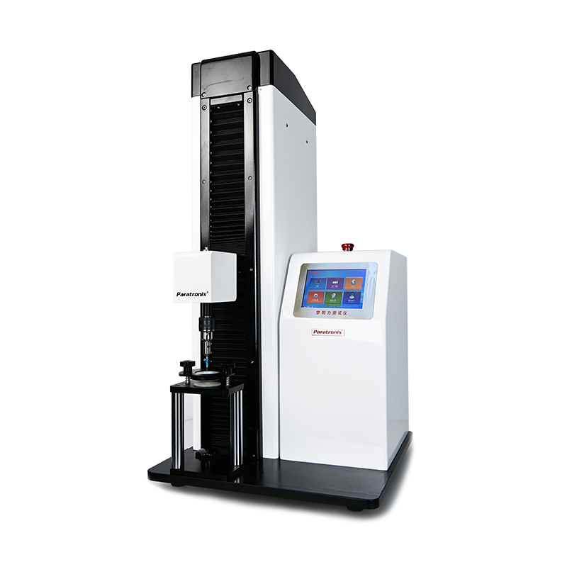
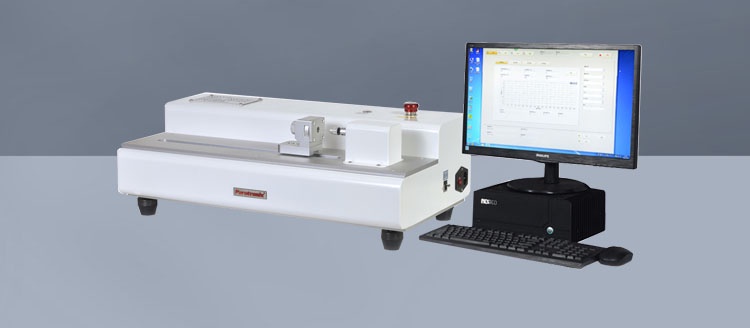
What Is An Artificial Skin Puncture Force Tester?
An artificial skin puncture force Tester is a mechanical testing system that measures the force needed for a probe, needle, or medical device to penetrate a skin substitute. A controlled drive moves the probe relative to a secured specimen while a force sensor records resistance against displacement. The resulting curve helps laboratories compare materials, device designs, and manufacturing batches under defined conditions.
Artificial skin is not one standardized material. Depending on the research objective, it may consist of silicone, polyurethane, elastomeric sheets, multilayer constructs, or other tissue substitutes. Thickness, stiffness, surface finish, and layer bonding influence the measured response. A surrogate can support comparative testing, but its behavior should not automatically be treated as equivalent to human skin or as evidence of clinical performance.
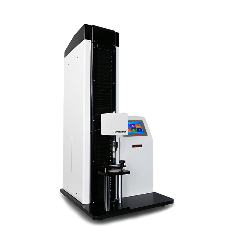
The equipment generally combines a motorized test stand, interchangeable load cell, probe holder, specimen fixture, and software for recording data. Some laboratories use a multipurpose tester configured for puncture; others specify a dedicated setup. The important distinction is whether the complete arrangement can reproduce the required motion, alignment, measurement range, and specimen support for the intended method.
Typical users include medical device developers, materials researchers, contract laboratories, and manufacturers evaluating incoming or finished components. Applications range from comparing needle tips and insertion aids to screening synthetic membranes used in training or product development. Results are most useful when the test question is specific, such as whether a design change alters peak insertion force under a fixed set of conditions.
How Puncture Testing Works
During a test, the instrument advances the probe at a specified speed toward the mounted specimen. The load cell records force as the material deforms and the probe penetrates. Depending on the specimen and geometry, the curve may show initial contact, increasing resistance, a distinct peak, a drop associated with puncture, and subsequent friction as the probe travels through the material.
Peak force is a common output, but it is not always the only relevant one. A method may also assess force at a defined displacement, penetration distance, or the area under a specified portion of the curve. The latter represents mechanical work over that interval, subject to the instrument and method used. Define each result before testing, including units, sign convention, and calculation limits.
A clear contact or preload rule is important because soft materials can deflect before the probe breaks through. Specify the starting position, approach speed, test speed, travel limit, and return behavior. The sample rate must be sufficient to capture a short puncture event; otherwise, the reported maximum may underestimate the actual peak. Confirm that the selected sensor range is appropriate for the expected forces.
Several factors can obscure a genuine material or design difference: a blunt or contaminated probe, poor alignment, uneven clamping, specimen creep, or variable environmental conditioning. Record probe geometry and condition, specimen dimensions, fixture opening, temperature, and any lubrication. Use a fresh test location for each penetration unless a validated procedure explicitly requires repeated punctures at the same site.
Main Test Configurations And Applications
Needle penetration setups hold the needle or device in a defined orientation above the surrogate. They are relevant to comparing tip geometries, coatings, and insertion conditions during development. The fixture should prevent needle movement without damaging the device, and the method should state insertion angle and depth. A controlled comparison also keeps needle lot, conditioning, and surrogate batch consistent where practical.
Probe-based membrane tests use a specified probe shape and support arrangement to characterize the puncture resistance of a sheet or layered material. They can help suppliers screen artificial skin formulations or monitor production consistency. Results from a rounded probe should not be directly equated with those from a sharp needle: the contact mechanics, failure modes, and measured forces can differ substantially.
An artificial skin puncture force Tester can also be configured for studies involving complete devices, provided the fixture accommodates their geometry and operating motion. For example, a team may compare insertion components using the same artificial skin and defined approach conditions. Such work is a development or quality-control application, not a substitute for a device-specific clinical evaluation or regulatory assessment.
Paratronix offers the PMT-C puncture force Tester as a related product and also lists multipurpose and medical packaging physical performance testers. For an artificial skin application, buyers should discuss the probe holder, specimen fixture, force range, software outputs, and test speed with the supplier before selecting a configuration. Suitability for a particular device or method should be confirmed against the actual test requirements.
Standards And Method Validation
There is no basis to assume that one published puncture standard covers every artificial skin and device combination. Select standards according to the product being evaluated, the specimen, and the intended claim. For example, ASTM F1306 addresses slow-rate penetration resistance of flexible barrier films and laminates. Its scope and prescribed conditions should be reviewed before considering it for a different material or application.
For relevant sterile hypodermic needles, ISO 7864 includes requirements and test methods applicable to those products; check the current edition and its scope for the device in question. A needle standard does not automatically validate a synthetic skin model. Likewise, using an artificial skin fixture does not by itself demonstrate compliance with a packaging, needle, or medical device standard.
Build a written method around the decision the test supports. Identify the specimen and probe, conditioning, fixture dimensions, speed, preload, data acquisition settings, result definitions, and acceptance criteria. Document sample selection and the number of replicates with a rationale. If comparing laboratories, exchange reference materials and procedures, then investigate differences in equipment, setup, operator technique, and specimen batches.
Validate or qualify the method to the extent appropriate for its intended use. Assess repeatability, sensitivity to meaningful changes, and the effect of relevant setup variables. Verify force and displacement measurement using traceable references at suitable intervals, and check the entire fixture for alignment and looseness. Establish control samples or other ongoing checks so that drift is detected before it affects decisions.
Selection Criteria For Buyers
Begin with the expected force range and the smallest difference the laboratory needs to distinguish. Request the load cell capacity, resolution, accuracy specification, and applicable calibration range; these terms are not interchangeable. An oversized sensor may be poorly suited to low-force work, while an undersized sensor risks overload. Check the complete system specification rather than relying on a sensor capacity alone.
Next, evaluate speed control, travel, displacement measurement, and acquisition rate against the planned test. Ask whether the software records raw force and displacement data, identifies the desired peak, and exports results in a usable format. For regulated workflows, review access controls, audit trail capability, and validation support where required. Do not assume these functions are included without confirmation.
Fixtures are often decisive. Provide the supplier with specimen thickness, dimensions, support opening, probe or device drawings, and the desired insertion angle. Ask how the system controls clamping pressure and alignment, and whether replaceable specimen holders are available. Confirm that the test area permits safe loading and that cleaning or changing samples will not introduce unnecessary variation or delays.
Before purchase, request a demonstration or feasibility assessment using representative specimens and devices. Review sample preparation, curve shape, repeatability, and any limitations observed; a favorable demonstration is not a full method validation. Clarify delivery scope, installation requirements, training, calibration arrangements, spare parts, and service response. Document unresolved configuration questions in the quotation or procurement specification.
Ownership Costs And Future Trends
The purchase price is only one part of total ownership cost. Include load cells, custom fixtures, software options, installation, operator training, calibration, maintenance, and consumable specimens or probes. Account for the time needed to establish and validate a method, investigate inconsistent results, and manage data. A multipurpose platform may support additional tests, but fixture changes and scheduling can affect its practical capacity.
Estimate return on investment using the actual workflow. Compare annual instrument and operating costs with the current cost of outsourced testing, shipping, operator time, and delays, while allowing for utilization and validation work. Better access to data may help development teams make decisions sooner, but assign a monetary benefit only when the organization has a defensible way to measure it.
Maintenance intervals should follow the manufacturer’s recommendations, laboratory quality system, usage, and observed equipment condition rather than a universal schedule. Inspect fixtures and probes before use, protect the load cell from overload, and investigate unexpected changes in control results. Arrange periodic calibration and document repairs, software changes, and requalification when they could affect measurement or data integrity.
Development is likely to continue toward more representative multilayer surrogates, improved data capture, and greater automation of repetitive testing. These changes can improve research workflows, but they also make material characterization and method comparability more important. To assess a paratronix configuration, share the test objective, specimen details, expected force range, and required records so the proposed equipment can be evaluated against a documented method.
 Building an ASTM-Aligned Plastic Film Puncture Test Method for Incoming QCPlastic films puncture force Tester guidance for building an ASTM-aligned incoming QC method with controlled conditions, reliable limits, and defensible film release decisions.
 Rubber Stopper Puncture Force Testing for Reliable Vial Closure Quality ControlRubber stoppers puncture force Tester solutions help verify vial closure performance, improve test repeatability, and support reliable injectable packaging quality control.
 When ASTM F1306 is suitable for laminated film puncture testingLaminated films puncture force Tester insights: learn when ASTM F1306 delivers reliable puncture resistance data, better laminate comparisons, and confident material specifications.
 What Does an Artificial Skin Puncture Force Tester Measure in Needle Testing?Artificial Skin Puncture Force Tester measures peak puncture, insertion, and withdrawal forces for reliable needle testing, helping improve quality control and product performance.
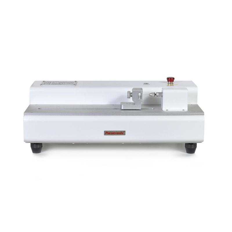
 PMT-C puncture force TesterThe PMT-C puncture Force Tester is a professional instrument in the pharmaceutical packaging testing series, specifically designed for measuring the puncture force of rubber stoppers.
It can also be used for puncture force testing of plastic films, laminated films, artificial skin, combination caps, and oral liquid caps. NTP-06 Artificial Skin Puncture TesterNTP-06 Needle Point and Artificial Skin Puncture Force Tester is based on "GB18671-2009" research and development, suitable for intravenous infusion needle, acupuncture needle, blood needle puncture force test.
Search by Keywords