




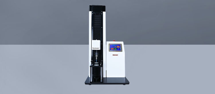
Validating a plastic film puncture test method against ASTM and ISO requirements is essential for generating reliable, repeatable data in packaging quality evaluation.
For technical evaluators, selecting a capable puncture force Tester of plastic films helps verify instrument performance, test parameters, and sample consistency across demanding packaging materials.
The central question is not whether a tester can produce a force value, but whether its method produces traceable, reproducible, and decision-ready evidence.
What Technical Evaluators Need to Validate First
When evaluating puncture resistance, technical teams usually need to confirm product suitability, supplier consistency, material change impact, and package protection performance during handling.
A defensible method must therefore link the reported peak force or puncture energy to a controlled specimen, fixture, probe geometry, test speed, and conditioning history.
ASTM and ISO standards provide an important framework, but they do not remove the need to establish whether a selected configuration represents the actual packaging risk.
For example, a thin pharmaceutical lidding film may fail differently from a multilayer retort pouch, high-barrier laminate, stretch film, or industrial protective film.
The appropriate method should simulate the relevant puncture mechanism, such as a sharp edge, a rounded protrusion, a concentrated point load, or accidental contact.
Technical evaluators should begin by defining the intended use of the data before comparing instruments, because application relevance determines most subsequent validation choices.
A method intended for incoming material approval may prioritize speed and routine repeatability, while failure investigation may require more detailed force-displacement curve analysis.
Similarly, a product-development method may need sensitivity to small laminate changes, whereas a release method may require clearly defined acceptance limits and operator controls.
The puncture force Tester of plastic films should support those objectives without requiring undocumented adjustments, improvised fixtures, or calculation steps outside the controlled procedure.
How ASTM and ISO Requirements Should Be Interpreted
ASTM and ISO documents are often used as references for sample preparation, apparatus design, test conditions, calculations, reporting, and laboratory consistency.
However, technical evaluators should verify the exact current edition and scope of each standard before claiming compliance for a specific film construction.
Some standards address puncture resistance through particular probe shapes or fixture arrangements, while others focus on impact puncture, tensile penetration, or related mechanical behavior.
ISO 6603, for instance, is frequently associated with puncture impact testing of plastics, but its applicability must be assessed carefully for flexible packaging films.
ASTM methods may be more relevant where a specified puncture probe, clamping arrangement, or controlled penetration rate matches the packaging material and expected use conditions.
Compliance language should be precise. A laboratory may test “in accordance with” an adapted procedure, while “compliant with” may require meeting every mandatory requirement.
That distinction matters during supplier qualification, customer audits, regulatory reviews, and disputes involving material performance or package integrity claims.
A validation protocol should identify the governing standard, any deliberate deviations, the technical rationale for those deviations, and the evidence supporting method suitability.
When no single standard fully matches the product, a documented internal method based on recognized ASTM or ISO principles can still be robust and auditable.
Choose a Tester That Controls the Variables That Matter
Instrument selection should focus on control and measurement capability rather than headline capacity alone. A higher load range does not automatically improve low-force film testing.
The load cell must have sufficient resolution and accuracy within the expected force range, particularly when evaluating thin films or subtle material differences.
Using a load cell near the lower extreme of its range can increase uncertainty and reduce discrimination between acceptable and marginal material lots.
Conversely, selecting an excessively sensitive load cell may create practical limitations when testing tougher laminates, reinforced films, or multilayer barrier structures.
The puncture force Tester of plastic films should permit controlled and repeatable crosshead speed, because penetration rate can change the apparent force response of polymeric materials.
Probe geometry is equally critical. Probe diameter, tip radius, angle, surface finish, and alignment influence stress concentration and the resulting puncture behavior.
A rounded probe may characterize resistance to blunt intrusion, while a sharper probe may better reveal vulnerability to cutting, pinholing, or localized damage.
Fixture design must prevent specimen slipping, uneven tension, wrinkling, and movement during penetration. These problems can cause misleading curves and artificially variable results.
Evaluate whether the tester supports interchangeable fixtures, traceable probe identification, repeatable clamping force, and documented setup positions for each qualified test method.
Data acquisition rate also matters. If sampling is too slow, the system may miss the true peak force or fail to capture meaningful pre-puncture deformation.
Define the Measurand Before Setting Acceptance Criteria
Many laboratories report only maximum puncture force, but peak force is not always the most informative property for a packaging performance decision.
Depending on the application, useful outputs may include force at puncture, displacement at puncture, energy to puncture, initial yield behavior, or force-displacement curve shape.
Energy can be particularly valuable when comparing films that exhibit different elongation characteristics, because two materials can have similar peak forces but different total resistance.
Displacement at puncture may reveal ductility changes, laminate delamination, orientation effects, or brittle behavior caused by aging, temperature exposure, and material formulation changes.
Technical evaluators should define the measurand in a method specification before establishing numerical limits, trending data, or comparing suppliers.
The calculation rule must also be explicit. For example, determine whether puncture is defined as the maximum force, a sudden force drop, a visual breakthrough event, or another curve criterion.
Without a clear event definition, different analysts may report different results from the same force-displacement trace, weakening repeatability and auditability.
The selected tester software should retain raw data and allow users to review curves, apply controlled analysis rules, and export results without manual transcription.
Build Method Validation Around Intended Use
Method validation should demonstrate that the procedure is fit for its intended decision, not merely that the instrument operates according to its specification.
A practical validation plan generally assesses accuracy or bias where a reference is available, repeatability, intermediate precision, linearity, range, robustness, and measurement uncertainty.
For puncture testing, a fully certified film reference material may not always be available. In that case, traceable instrument calibration and comparative studies become especially important.
Load verification should use calibrated force standards across the relevant operating range. Travel or displacement verification should be performed using traceable dimensional references.
The fixture and probe should be inspected for wear, damage, contamination, and alignment. A slightly damaged tip can significantly change results for thin film structures.
Repeatability evaluates variation when the same operator, equipment, materials, and short test period are used. It indicates whether the basic setup is stable.
Intermediate precision considers realistic laboratory variation, including multiple days, operators, instrument setups, and sometimes different qualified instruments or locations.
This broader assessment is often more valuable for technical evaluators because routine quality data are rarely generated under ideal single-operator conditions.
Robustness studies should intentionally examine reasonable variation in settings, including speed, clamp pressure, conditioning time, specimen orientation, and probe replacement.
The goal is not to prove that every variation is harmless. It is to identify parameters that require tight control in the standard operating procedure.
Control Specimens, Conditioning, and Sampling Discipline
Film puncture results can be highly sensitive to specimen preparation. A well-calibrated instrument cannot compensate for inconsistent samples or uncontrolled environmental exposure.
Sampling should reflect the material structure and production process. Films can vary across web width, machine direction, transverse direction, roll position, and coating zones.
A validation protocol should state the number of rolls, locations, replicates, and orientations needed to characterize expected material variation appropriately.
Specimens should be cut cleanly without edge damage, folds, nicks, fingerprints, or residual stress caused by unsuitable cutting tools.
Dimensions must be adequate for the fixture. Material extending beyond the clamping area should not introduce drag, slack, or contact with surrounding equipment.
Conditioning temperature and relative humidity should be specified, especially for hygroscopic films, coated structures, adhesives, paper-plastic composites, and pharmaceutical packaging components.
Where puncture performance is evaluated at refrigerated, heated, or use-condition temperatures, the procedure should control sample equilibration and transfer time to the test fixture.
Sample orientation should never be assumed irrelevant. A multilayer film may show different response depending on whether the probe contacts the sealant side or outer substrate.
Machine-direction and transverse-direction testing may also reveal orientation effects that are concealed when results are pooled into a single average.
Establish Repeatability With a Meaningful Study Design
A small group of identical specimens can make an instrument appear highly repeatable, but that design may fail to represent the variation encountered in actual production testing.
Use materials that span the intended range, including low, nominal, and high puncture resistance where possible. This helps verify capability across the decision range.
Replicate counts should be justified statistically and operationally. Too few specimens can hide variation, while excessive testing can consume material without improving the decision.
Review both numerical results and individual force-displacement curves. A similar average force can mask different failure mechanisms, slipping, abnormal deformation, or inconsistent puncture events.
Calculate standard deviation, relative standard deviation where appropriate, confidence intervals, and repeatability limits according to the laboratory’s statistical procedures.
Do not automatically reject an outlier because it is inconvenient. Investigate whether the result reflects specimen variation, an observable setup issue, or a real material defect.
Any exclusion rule should be predefined and supported by documented evidence. Post-test deletion of difficult results can undermine the credibility of validation data.
For routine use, include a control material or verification specimen that can detect drift in load measurement, fixture condition, probe condition, or operator technique.
Use Measurement System Analysis to Support Decisions
For supplier approval and specification control, technical evaluators need to know whether observed differences are caused by the material or the measurement system itself.
A gauge repeatability and reproducibility study can help quantify the proportion of total variation attributable to equipment and operators.
Although standard Gage R&R practices may require adaptation for destructive tests, the underlying principle remains useful: separate measurement variation from part-to-part variation.
Destructive puncture testing prevents repeated measurement of the exact same specimen, so laboratories may use carefully designed nested or randomized studies instead.
Statistical support should be selected by a qualified analyst and aligned with the test design, material homogeneity, and intended use of the result.
The important practical conclusion is whether the system can distinguish meaningful performance differences near the product specification or supplier comparison threshold.
If the method variation is large relative to the tolerance window, tighter specifications may create false rejects, false accepts, and unnecessary disputes.
A capable puncture force Tester of plastic films provides the data integrity needed for this analysis, but study design and operator discipline determine its real value.
Document Deviations and Data Integrity Requirements
Validation records should allow another qualified person to understand exactly how the method was performed, evaluated, approved, and maintained after initial implementation.
The protocol should identify the instrument model, serial number, load cell, fixture, probe, software version, calibration status, environmental conditions, and sample material details.
It should also define acceptance criteria before testing begins. Criteria may address calibration tolerances, precision targets, allowable curve characteristics, and robustness outcomes.
Final reports should include raw-data traceability, statistical analysis, deviations, investigation outcomes, conclusions, and approval signatures consistent with the organization’s quality system.
For regulated pharmaceutical packaging operations, electronic records and audit trails may be particularly important. Confirm that user access, data retention, and result modification controls are suitable.
Software should provide clear traceability for test methods, parameter changes, user actions, and exported reports where data are used in quality decisions.
Instrument qualification should also be maintained through scheduled calibration, preventive maintenance, functional checks, and change control when probes, software, fixtures, or procedures change.
Common Validation Failures That Create Misleading Results
A frequent failure is relying on a standard name without confirming whether the standard’s specimen type, test geometry, or loading mode actually fits the film application.
Another issue is validating a tester using a single material, then applying the method to substantially different thicknesses, laminate structures, or puncture mechanisms.
Some laboratories use a fixed crosshead speed because it is convenient, without demonstrating that the selected speed produces relevant and stable discrimination for their materials.
Inconsistent clamping is another major source of error. Differences in tension, clamp pressure, and specimen centering can alter measured force before true puncture occurs.
Technical teams should also avoid acceptance limits based solely on historical averages. A meaningful limit requires knowledge of product needs, material variation, and measurement uncertainty.
Finally, reporting only one number can conceal failure modes. Curve review often identifies delamination, slippage, tearing, and abnormal behavior before a summary statistic does.
A Practical Evaluation Checklist for Equipment Selection
Before purchasing or qualifying equipment, ask whether the tester supports the selected ASTM or ISO-based method without unverified accessories or nonstandard setup compromises.
Confirm the available force ranges, measurement accuracy, resolution, displacement accuracy, data acquisition rate, and crosshead speed control across the actual operating conditions.
Review probe options carefully. The supplier should identify dimensions, materials, tolerances, surface finish, replacement procedures, and traceability for each probe configuration.
Assess fixture repeatability by observing how specimens are positioned and clamped. The process should be simple enough to perform consistently in routine laboratory work.
Ask to review raw force-displacement curves, not only polished summary reports. This demonstrates whether the system captures events clearly and supports meaningful investigation.
Evaluate software for method locking, user permissions, audit trails, report customization, export formats, and raw-data retention according to laboratory quality requirements.
Support capability also matters. A qualified supplier should provide application guidance, installation assistance, calibration support, service response, and documentation suitable for validation work.
Paratronix Instruments Co., Ltd. provides packaging testing solutions for pharmaceutical packaging, plastic packaging materials, and high-barrier materials where controlled mechanical testing is required.
Conclusion: Validation Must Demonstrate Decision Confidence
ASTM and ISO references provide a valuable foundation, but successful puncture method validation depends on aligning the standard, equipment configuration, material behavior, and intended quality decision.
Technical evaluators should prioritize measurement control, suitable probe and fixture geometry, sample discipline, repeatability studies, data integrity, and documented deviations from published methods.
A properly qualified puncture force Tester of plastic films does more than generate a peak-force number. It supports defensible supplier comparisons, material release decisions, troubleshooting, and package risk evaluation.
When the method is built around actual packaging hazards and validated against defined acceptance criteria, puncture data become reliable engineering evidence rather than isolated laboratory measurements.