




Recent Posts
 How humidity affects results from a gas transmission rate testerOct 20, 2026
 What Does a Metallic Medical Bone Screw Tester Actually Measure?Oct 20, 2026
 How to perform an ampoule break force test according to ISO 9187-1Oct 19, 2026
 How Bone Screw Self-Tapping Testers Measure Axial Force and Tapping TorqueOct 17, 2026
 ASTM F543 Bone Screw Pull-Out Testing: Setup and Reporting RequirementsOct 17, 2026

A bone screw can resist twisting yet still pull out of a test material relatively easily. It can also require substantial insertion torque without providing proportionally stronger fixation. When reviewing a test report, treating these measurements as interchangeable can lead to the wrong conclusion about screw performance.
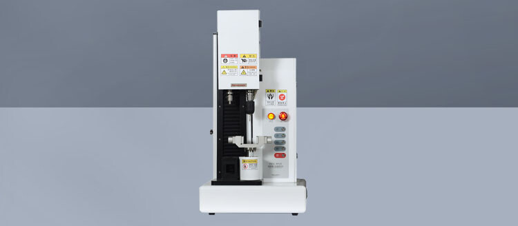
A metallic medical bone screw tester measures mechanical responses under defined loading conditions. Depending on its sensors, controls, and fixtures, it can measure torsional properties, driving and removal torque, axial pullout strength, and self-tapping performance. These measurements answer different questions; no single result establishes overall implant quality or predicts clinical success.
The measurement depends on the test setup
The equipment does not directly measure “bone fixation quality.” Its sensors record quantities such as torque, angular displacement, axial force, and linear displacement. Software then uses those signals to calculate results defined by the selected test method.
A torsional test typically restrains part of the screw while rotating its head. An insertion test drives the screw into a prepared material. A pullout test applies tension along the screw axis until fixation fails. Although all three involve the same type of implant, their load paths and failure mechanisms are different.
A machine equipped only for torque testing cannot automatically perform axial pullout testing. Likewise, a universal testing machine with a tensile load cell does not become a complete bone screw testing system without the appropriate fixtures, rotational capability where needed, and test controls.
Torsional testing: resistance to twisting, not resistance to pullout
During screw placement, torque travels from the driver through the screw head and into the shaft. A torsional test examines the screw’s response to this twisting load under a specified gripping arrangement. The instrument records a torque–rotation curve rather than simply displaying one strength number.
Which results come from the curve?
Torsional yield strength identifies the transition toward permanent deformation using the definition prescribed by the method. Maximum torque is the highest torque sustained during the test. Breaking angle describes the angular rotation reached at fracture, as defined by the procedure. Each result describes a different aspect of behavior.
A screw may sustain a relatively high maximum torque but undergo limited rotation before breaking. Another may deform through a greater angle before fracture. Neither observation alone establishes which design is appropriate: dimensions, material condition, intended use, and the complete test evidence remain relevant.
The gripping arrangement matters because it establishes the loaded length and where twisting occurs. Changing the exposed length or clamping location can change the measured rotation and failure location. Machine compliance and fixture movement can also contribute to recorded angular displacement.
Inspect the specimen after testing. Driver disengagement, head damage, shaft fracture, and slipping within the clamp are not equivalent events. If the fixture slips before the screw fails, the recorded peak may describe the setup’s limitation rather than the screw’s torsional capacity.
Insertion and removal torque describe an interaction
Insertion torque is the rotational resistance encountered as the screw advances into the specified test material. It depends on the screw, but also on the material, pilot hole, thread preparation, insertion depth, alignment, and operating conditions.
This distinction becomes important when two reports show different torque values for apparently similar screws. A smaller pilot hole or a different substrate may change resistance without any change in screw manufacturing. Before attributing the difference to design quality, compare the preparation and test conditions.
The torque trace can reveal more than a peak value. It may show changes during initial engagement, continued advancement, or seating. However, seating against a surface or plate can introduce additional contact and friction. A peak associated with seating should not automatically be treated as the torque required to advance the threads through the material.
Removal torque measures resistance during reverse rotation under the specified procedure. It is not necessarily equal to insertion torque: the preceding insertion may have cut, compressed, or damaged the surrounding material. Reusing the same hole therefore changes the test condition.
Higher insertion torque does not, by itself, prove stronger fixation. Excessive resistance can also consume the available margin before torsional damage or driver-interface failure. Comparing driving requirements with torsional capacity can inform engineering evaluation, but these laboratory results do not establish a universal surgical torque limit.
Axial pullout strength tests the screw–material interface
In an axial pullout test, the screw is embedded to a controlled depth and loaded in tension along its axis. The instrument records force against displacement. The maximum force reached during extraction is commonly reported as pullout strength, subject to the selected method’s definition.
Unlike torsional testing, this test often challenges the surrounding material and thread engagement rather than the metallic shaft alone. Threads may shear through the substrate, the material may fracture, or the screw may lose engagement through another mechanism. The failure mode helps explain what the peak force actually represents.
Several setup details strongly affect interpretation:
- Test material: Its type, density, structure, and condition influence how it supports the threads.
- Engagement: Insertion depth and the portion of thread embedded determine the interface being loaded.
- Hole preparation: Pilot drilling and tapping alter the material available for thread engagement.
- Alignment and support: Off-axis loading introduces bending, while specimen restraint can influence local deformation.
Displacement also requires care. Crosshead movement may include deformation of fixtures and the machine load train, not just screw movement relative to the substrate. A reported stiffness or displacement at failure therefore needs a clear measurement definition.
Standardized synthetic materials can support controlled comparisons, but they do not reproduce every feature of living bone. Biological specimens introduce their own variability. Results from different substrates should not be treated as directly interchangeable merely because both are labeled “pullout strength.”
Self-tapping performance is a separate question
A self-tapping screw is intended to form a mating thread in a prepared hole rather than relying entirely on a previously tapped thread. Testing this function examines whether the screw can initiate cutting and advance under defined conditions.
Depending on the prescribed procedure, the equipment may monitor axial force, rotational resistance, and advancement. The axial force needed to establish tapping is different from the torque required to continue insertion. A report should identify the measured endpoint rather than using the broad phrase “self-tapping ability” without explanation.
Pilot-hole geometry and substrate properties are especially important here. An unsuitable hole can change the apparent performance of the cutting features. Repeated attempts in a damaged hole cannot be assumed equivalent to tests in fresh, consistently prepared holes.
Where ASTM F543 fits—and what the reference does not prove
ASTM F543 addresses metallic medical bone screws and includes methods for evaluating properties such as torsional behavior, driving torque, axial pullout strength, and self-tapping performance. It provides a framework for making these measurements under specified conditions.
The phrase “ASTM F543 testing” is incomplete unless the report identifies the applicable test method and standard edition. A system configured for one method may lack the hardware or control functions needed for another. Relevant details include specimen preparation, fixtures, test material, loading conditions, calculations, and any deviations.
A standard reference also does not automatically supply a pass/fail decision for every screw design or intended application. The applicable requirements and acceptance criteria must be established for the evaluation being performed. A laboratory can generate a valid measurement without that measurement alone demonstrating suitability for clinical use.
When checking an equipment claim, ask which specific methods the proposed configuration supports. A suitable torque range is useful, but it does not establish correct alignment, adequate angular measurement, appropriate pullout capability, or a conforming test procedure.
Reading a report without overinterpreting the numbers
Start with the question the test was designed to answer. If the concern is screw breakage during driving, torsional behavior and insertion demands are relevant. If the concern is axial fixation in a particular substrate, pullout testing addresses that interface more directly. Neither substitutes for the other.
Next, check whether the comparison is controlled. Screws with different diameters, thread geometries, engagement depths, or material conditions may produce different results for several reasons at once. That comparison can still be useful, but it cannot necessarily isolate the effect of one design feature.
Review individual curves, specimen counts, variation, and failure observations alongside averages. An isolated peak can conceal slipping, premature seating, an irregular engagement event, or a different failure mode. Those observations may change the interpretation more than a small difference between reported means.
Units deserve a direct check: torque is not force, and rotational displacement is not axial displacement. Results expressed in different torque units must be converted before comparison. Even matching units do not make tests comparable when preparation or loading conditions differ.
What remains outside the tester’s scope?
These mechanical tests do not directly measure healing, osseointegration, infection risk, biological compatibility, or clinical outcomes. A single axial pullout test also does not establish fatigue resistance under repeated loading, and a static torsional test does not characterize every loading condition an implant may experience.
Other questions may require separate methods: cyclic loading, bending, corrosion, dimensional inspection, or evaluation of a screw within a larger fixation construct. The need depends on the device and intended use, not on how many result fields appear in the tester’s software.
For an initial equipment assessment, define the required measurement before selecting the machine. Then confirm the sensing range and resolution, fixture geometry, alignment, control mode, calibration, and reporting functions needed for that method. A useful specification states not just “bone screw testing,” but which property will be measured, under which conditions, and how invalid tests or alternative failure modes will be identified.
Leave A Reply
Search by Keywords