Recent Posts
 Maintenance methods for thin film thickness detection instruments2025-12-15
 Method for detecting the opening tension of food chain self sealing bags2025-12-03
 Packaging industry testing instrument - moisture permeability tester2025-11-26
 What testing instruments are used for testing the heat sealing performance of thin films?2025-11-20
 Precautions for using negative pressure seal detector2025-11-10
Standard Test Method for Nondestructive Detection of Leaks in Packages by VacuumDecay Method
1. Scope
1.1 7est Packages-Packages that can be nondestructivelyevaluated by this test method include:
1.1.1 Rigid and semi-rigid non-lidded trays.1.1.2 Trays or cups sealed with porous barrier liddingmaterial.
1.1.3 Rigid, nonporous packages.
1.1.4 Flexible, nonporous packages.
1.2 Leaks Detected This test method detects package leaksby measuring the rise in pressure (vacuum loss)in an
enclosedevacuated test chamber containing the test package, Vacuumloss results from leakage of test package
headspace gasesand/or volatilization of test package liquid contents located inor near the leak. When testing for
leaks that may be partially orcompletely plugged with the package's liquid contents, the testchamber is evacuated to
a pressure below the liquid's vaporization pressure, All methods require a test chamber to containthe test package and
a leak detection system designed with oncor more pressure transducers, Test method sensitivities citedbelow were
determined using specifie product-package systems selected for the precision and bias studies summarized inTable 1.
Table 1 also lists other examples of relevant product.package systems that can be tested for leakage by vacuumdccay.
1.2.1 Trays or Cups (Non-lidded) (Air Leakage) Hole orerack defects in the wall of the tray/cup of at least $0 μm indiameter
can be detected, Nonlidded trays were tested at aTarget Vacuum of-4-E4 Pa(-400 mbar).
1.2.2 Trays Sealed with Porous Barrier Lidding Material(Headspace Gas Leakage) Hole or crack defects in the walof the tray/cup
of at least 100 um in diameter can be detectedChannel defects in the seal area (made using wires of 125 umin diameter)can be
detected. Severe seal bonding defects inboth continuous adhesive and dot matrix adhesive packagesystems can be detected,
Slightly incomplete dot matrix adhesive bonding defects can also be detected. All porousbarrier lidding material packages were
tested at a TargetVacuum of-4.E4 Pa (-400 mbar). The sensitivity of the test forporous lidded packages is approximately E-2
Pa·m's"" using acalibrated volumetric airfow meter.
1.2.3 Rigid, Nonporous Packages(Headspace GasLeakage) Hole defects of at least 5 um in diameter can bedetected, Plastic bottles
with serew caps were tested at a targelvacuum of -5.E4 Pa (-500 mbar). Using a calibrated volumetric airfow meter, the
sensitivity of the test is approximatelyE-3.4 Pa·m''s.Air-flled glass syringes were tested at a targetvacuum of -7.5-E4
Pa(+250 mbar absolute) and again at atarget vacuum of about +l mbar absolute. The sensitivity ofboth tests is approximately
E4.1 Pa·m’.s' using a calibratedvolumetric airlow meter.
1.2.4 Rigid, Nonporous Packages (Liquid Leakage) Holedefects of at least S um in diameter can be detected. Thisietection limit
was verified using a population of water-filledglass syringes tested at a target vacuum of about +l mbarabsolute.
1.2.5 Flexible, Nonporous Packages (Gas or LiguidLeakage)-Such packages may also be tested by the vacuumdecay method,
Hole defects of at least $ um in diameter can bedetected for gas leakages. This detection limit was verifedusing a population
of packs as presented in Table ll.
1.3 Test Results-Test results are qualitative (AcceptReject).Acceptance criteria are established by comparingquantitative
baseline vacuum decay measurements obtainedfrom control, non-leaking packages to measurements obtainedusing
leaking packages, and to measurements obtained with theintroduction of simulated leaks using a calibrated gas fowmeter.
1.4 The values stated in Sl units are to be regarded asstandard, No other units of measurement are included in thisstandard.
4. Summary of Test Method
4.1 The test package is placed in a test chamber to whiehvacuum is applied. The chamber is then isolated from thevaeuum
source and a pressure transducer (absolute or gauge)alone or in combination with a second differential pressuretransducer,
is used to monitor the test chamber for both thelevel of vacuum, as well as the change in vacuum over time.Vacuum decay,or
rise in chamber pressure, is a result ofpackage headspace gas being drawn out of the package throughany leaks present, plus
background noise. Vacuum decay canalso result from the volatilization of packaged liquid thatpartially or fully occludes the
leak path. In this case, vacuumdecay will only occur if the chamber test pressure is loweredbelow the liguid's vaporization
pressure.
4.2 Porous barrier lidded tray or cup packages are tested forleaks located in the tray or cup, and at the lidding material/trayseal
junction, Leaks in the porous lidding material itself cannotbe detected, When testing such packages, steps are taken tophysically
mask or block the porous barrier surface to preventthe migration of package gas through the porous lid. Thesesteps may require
some sample preparation, depending on themasking approach required, but must be nondestructive andnoninvasive, Vacuum
decay from porous barrier lidded pack-ages may potentially include background noise from gastrapped between the lidding
material and the masking surface,or from transverse gas fow through the porous barrier materialitself at the lid/tray seal junction.
4.3 The sensitivity of a test is a function of test packagedesign,transducer(s)'sensitivity,test chamber design, testsystem design,
and critical test parameters of time and pres-sure. The test system and leak test parameters selected for anygiven product-package
system must be based on the package'scontents (liguid or solid with signifcant or little gasheadspace), and the nature of the
package (fexible or rigid,porous or nonporous).Instruments with more sensitive pres-sure transducers and with minimal void
volumes within the testchamber and the test system have the potential to detect thesmallest lcaks, Lengthening test time
enables smaller gaseousleaks to be detected. Minimizing pressure variation back-ground noise can also improve test sensitivity.
For porousbarrier lidded packages, masking techniques will minimizebackground noise, For fexible or semi-rigid packages,
restrict-ing package expansion via properly designed test chamberslessens noise, Background noise may also occur upon
releaseof residual gases or vapors trapped in the test system orbetween test package components, Such noise can be
differen-tiated from actual leakage by lengthening the time to reachinitial vacuum or lengthening equalization time.
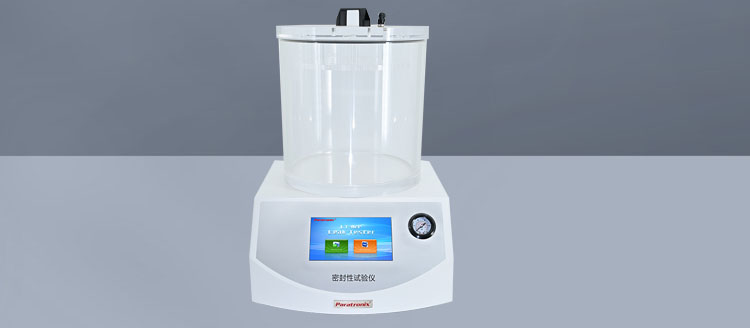
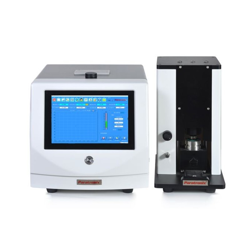
Testing instruments:MLT- V100 Micro-Leakage Non-Destructive Seal Tester
6. Apparatus
6.1 Vacuum Decay Leak Detection Apparatus-The vacuumdecay leak apparatus includes a test chamber connected to
avacuum decay test system and a volumetrie airfiow meter.
6.2 7est Chamber-The test chamber has a lower compart-ment (lower tooling) designed to nest the test packagc, and
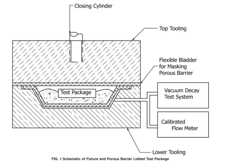
anupper lid (top tooling)for closing the test chamber. Fig.1illustrates a test chamber designed for testing packages
withporous barrier lidding material, The test fixture upper lidconsists of a fexible bladder to mask the package's
porousbarrier during the test cyele. Figs,2 and 3 illustrate testchambers designed for testing rigid, nonporous packages,
Inthe latter two cases, there is no fexible bladder.6.2.1 Tray Nest or Lower Tooling-The bottom half of thetest chamber is
dimensionally designed to closely nest the testpackage, while still allowing for easy gas fow around the testpackage.
Without ready gas flow around the package, leakagesites can be blocked, Conversely, the larger the gap betweenthe
test chamber and the test package, the less sensitive the leaktest, as vacuum deeay from package leakage will be
minimizedin a larger net test chamber volume.6.2.2 Upper Lid or Upper Tooling The upper lid is de.signed to tightly
seal the closed test chamber during thevacuum cyele.
6.3 Vcuum Decay Test System-The vacuum decay testsystem includes a vacuum source for establishing the required
vacuum within the chamber at the beginning of the test cyele,and a pressure transducer(absolute or gauge), alone or
incombination with a second differential pressure transducer, formonitoring the vacuum level as well as the pressure
change asa funetion of time during the test cyele. Test systems intendedfor higher target vacuums, such as +l mbar or
less, should bedesigned for greater target pressure measurement accuracy,with minimal system leakage and
outgassing that may affecttest measurement signal to noise ratio.
NoTE 2-DifTerent leak test instruments may utilize diferent pressuretransducer types and combinations, and vacuum
pumps based on thepackage types tested (for exampie, rigid versus nonrigid, porous versusnonporous) and the
vacuum level that is required to performn the test.
6.3.1 Absolute versus Gauge Transducer-All instrumentsincludes a single 1000 Torr transducer for monitoring testpressure
throughout the test cycle. An absolute transducer ispreferred over a gauge transducer when precise, true pressurereadings
are required (that is, not subject to atmosphericpressure changes from weather or altitude). Such is the easewhen
performing high vacuum liquid leak tests.6.3.2 Diferential Transducer-A second differential pres.sure transducer may
be employed for measuring the smallestdetectable leaks in rigid or semi-rigid nonporous packages.6.3.3 Veuu Source-A
vacuum pump is selected based onthe target vacuum level that must be achieved within theallotted time frame given the
test system airspace.
6.4 Mask or Block-The porous barier lidding material ofpackages must be masked or blocked during testing to mini.mize
egress of air from the package through the lidding.Various masking techniques may be used, including a testchamber
designed with a fexible bladder in the upper tooling(refer to Fig. 1).
6.5 Vlumetric Airfow Meter-An adjustable volumetricairflow meter is placed in-line with the test chamber tointroduce an
artificial leak at variable rates. It is recommendedthat an airflow meter be used to verify the leak test's sensitivity.NoTE 3-Refer
to Annex A2 for further information about volumetricairflow meter use for verifying leak test sensitivity.
Leave A Reply
Search by Keywords

