




Recent Posts
 What does ASTM F543 require of a bone screw torque tester?Oct 23, 2026
 Can a WVTR Tester Test Aluminum Foil Laminates?Oct 22, 2026
 How Do Temperature and Humidity Affect WVTR Lab Comparisons?Oct 22, 2026
 Why Do WVTR Results Differ Between Laboratories?Oct 22, 2026
 What Does a Torque Tester Measure in Bottle Cap Quality Control?Oct 22, 2026
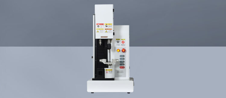
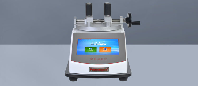
A Bone Screw Torque Tester is suitable for ASTM F543 work when its complete test configuration can perform the applicable method for the screw being evaluated. Measuring peak torque alone does not establish suitability. The machine, fixtures, drive connection, control functions, measurement channels, and data processing must together support the specified procedure and its required results.
For quality control and safety teams, the first decision is which screw property needs verification. ASTM F543 addresses metallic medical bone screws and includes separate methods for torsional properties, driving torque, axial pullout strength, and self-tapping performance. These methods place different demands on the equipment. A system configured for torsional failure testing may need additional fixtures, axial control, or measurement capability before it can support insertion or self-tapping tests.
Equipment claims should therefore be assessed against the applicable edition of ASTM F543, the selected method, and the intended screw range. A supplier’s statement that a machine is “ASTM F543 compliant” is a starting point for that assessment; it does not demonstrate that every offered configuration can perform every test.
Start with the method and the result it must produce
Torsional testing evaluates how the screw responds when torque is applied under defined gripping and loading conditions. The useful output includes the torque–rotation relationship and the torsional properties determined from it. A machine that displays only the highest torque reached can leave the laboratory without the information needed to determine other required properties or examine how failure developed.
Driving torque testing concerns the torque associated with inserting and removing a screw in a specified test medium and preparation. Here, the drive interface, alignment, insertion conditions, and test material become part of the measurement. A torque reading obtained while a screw enters an arbitrary block cannot automatically be treated as an ASTM F543 result.
Self-tapping testing adds another concern: how the screw initiates cutting and advances under the applicable axial and rotational conditions. Depending on the selected procedure, axial loading and its measurement are essential equipment considerations. A rotary torque machine with an uncontrolled vertical feed should not be assumed suitable merely because it can turn the screw.
Axial pullout testing applies a different loading mode. It requires an appropriate force-testing arrangement, specimen support, alignment, and displacement measurement as specified by the method. Some integrated platforms can accommodate several loading modes, but a conventional torque tester does not acquire pullout capability through software selection alone.
This distinction prevents a common purchasing error: specifying “ASTM F543 testing” without identifying the required methods. Before comparing machines, define the screw families, intended evaluations, applicable standard edition, and required reported properties. Those decisions establish the equipment specification.
Evaluate measurement quality across the working range
Torque capacity must accommodate the anticipated test, including failure where the method requires it. Capacity also needs to suit the lower end of the product range. A high-capacity transducer may survive demanding tests while providing insufficient measurement performance for a much smaller screw. Assess accuracy, resolution, and calibration coverage at the torques the laboratory will actually measure.
Resolution and accuracy describe different things. A display may show many decimal places without measuring to that level of certainty. Ask for the stated measurement performance, its basis, and the usable calibrated range. Where the selected method specifies equipment tolerances, compare those requirements directly with the proposed configuration rather than accepting an overall machine specification.
Angular displacement deserves similar scrutiny. Establish where rotation is measured and how the reported angle relates to the specimen. Rotation at the motor can include deformation or movement in the transmission, fixtures, and drive connection. Those contributions can affect the torque–angle curve, particularly when evaluating stiffness or properties derived from an offset construction.
The fixture arrangement should therefore be sufficiently rigid and secure for the intended measurements. If compensation or correction is proposed, its basis should be documented and its use consistent with the method. Software cannot reliably reconstruct specimen behavior from an unstable mechanical connection.
Data acquisition must capture the events used to calculate the reported properties. An acquisition rate suitable for a slow, smooth loading curve may miss a short torque peak or poorly describe abrupt failure. Request evidence that the measurement and recording settings suit the specified loading conditions. Filter settings also matter: excessive smoothing can change a peak, obscure slipping, or alter the apparent shape of the curve.
Calibration should cover the channels used in the test, including torque and, where applicable, angle and axial force. Review traceability, calibration range, measurement uncertainty, and the configuration covered by the certificate. A calibrated transducer supports measurement confidence, but the assembled setup still needs checks for alignment, movement, and correct operation.
Fixtures and loading conditions determine whether the result is meaningful
For torsional testing, specimen gripping is a central part of the procedure. The applicable method governs how the screw is held and the portion subjected to loading. Changes in engagement or exposed geometry can change the measured response. A convenient clamping position chosen by the operator may produce a repeatable result that does not represent the specified test.
The fixture must prevent unintended movement without introducing damage that dominates failure. Slippage can resemble specimen rotation; aggressive gripping can create an artificial failure location. After testing, the operator should be able to distinguish screw failure from grip movement, fixture failure, or damage caused during setup. Recording the failure location helps make that distinction reviewable.
The connection to the screw head also requires attention. Driver fit, engagement depth, wear, and coaxial alignment can influence torque transmission. If the driver disengages or damages the recess before the intended endpoint, the recorded maximum may describe the drive connection’s limitation. The laboratory needs a defined approach for identifying and handling such events.
Driving and self-tapping tests require controlled interaction between the screw and test medium. Relevant variables include the material specified by the method, specimen dimensions, support, hole preparation where applicable, insertion depth, and rotational conditions. A change in block preparation can shift the result even when the torque measurement remains stable.
Axial loading needs particular care. During insertion, the screw advances along its axis, and the equipment must accommodate that motion while maintaining the prescribed conditions. A rigidly constrained head, uncontrolled operator pressure, or unsuitable feed arrangement can introduce forces that affect the measured torque. For self-tapping evaluation, verify that the proposed system can apply, measure, and control axial loading as the applicable procedure requires.
Programmed speed alone is not proof of controlled loading. The machine should maintain the required behavior as resistance changes, including near engagement and failure. Review the available speed range, control performance, travel, and stopping behavior against the method. Published numerical requirements should be taken from the applicable standard edition; a value copied from a brochure or an older laboratory procedure may refer to a different test condition.
These setup details also affect comparisons between laboratories. Two results labeled “maximum torque” may come from different gripping conditions, test media, insertion depths, or processing rules. Before treating a difference as evidence of a product change, establish that the measurements represent the same procedure and property.
Require software that preserves the evidence behind the result
The software should calculate each reported property using the definitions and analysis approach required by the selected method. A generic “yield torque” function may use an algorithm developed for another application. The laboratory should understand how the system identifies the relevant points on the curve, establishes any reference slope, and handles the endpoint.
Retaining the torque–angle record makes these calculations reviewable. Where axial force or other channels are relevant, retaining their synchronized records can help explain unusual behavior. A peak value by itself offers little basis for distinguishing normal specimen failure from driver disengagement, slipping, or an interrupted test.
Check that data exports preserve units, specimen identification, test settings, and sufficient measurement detail for review. The report should identify the standard edition and method used, the specimen, relevant setup conditions, calculated results, and any deviations or abnormal events. Traceable records help a quality team decide whether an unexpected result reflects the product, the procedure, or the equipment.
Additional record controls may be needed under the laboratory’s quality system. User permissions, revision history, approval controls, and electronic signatures can support those needs, but they should be assessed separately from the mechanical test requirements. Their presence does not establish that the machine performs the ASTM method correctly.
The same separation applies to acceptance criteria. ASTM F543 provides test methods and requirements within its scope; invoking it does not automatically supply a universal pass/fail torque for every screw design. Acceptance decisions must use the applicable product requirements, design inputs, or other justified criteria. A software template containing a default limit is not sufficient justification for releasing a product.
Make the equipment claim specific enough to verify
A useful supplier assessment asks the manufacturer to map the proposed equipment to the methods the laboratory intends to run. The response should identify the supplied fixtures, measurement ranges, control functions, analysis routines, and any additional equipment needed. Any unsupported method or restricted screw geometry should be clear before purchase.
For a practical demonstration, use representative specimens spanning the intended range where feasible. Review the complete setup and recorded curves, not just the final report. A demonstration can reveal inadequate driver access, limited axial travel, unstable gripping, or poor measurement performance near the lower end of the range. It supports equipment evaluation without replacing the laboratory’s own qualification and procedure controls.
The laboratory should then document a procedure that connects the standard to daily operation: specimen preparation, fixture selection, loading settings, calculation rules, equipment checks, and handling of abnormal tests. Operators need enough instruction to recognize an invalid setup or interrupted test before treating the displayed result as usable evidence.
For an existing Bone Screw Torque Tester, the same review can identify whether the gap is a fixture, an additional measurement channel, a control limitation, or software analysis. Some gaps can be addressed through a documented upgrade. Others require a different platform because the machine cannot reproduce the required loading conditions.
The defensible endpoint is a demonstrated match between the selected ASTM F543 method and the installed test configuration. A quality team should be able to explain how the screw was loaded, how torque and rotation were measured, how the reported property was calculated, and why the record is valid. That is the evidence an equipment claim needs to support.
Leave A Reply
Search by Keywords