




Recent Posts
 Where should wall thickness be measured on a medicine bottle?Nov 06, 2026
 Can a wall thickness tester measure the base of a medicine bottle?Nov 06, 2026
 How does a medicinal bottle wall thickness tester work?Nov 06, 2026
 Can an oxygen permeability tester measure finished packages?Nov 05, 2026
 What ASTM D3985 requires from an oxygen permeability testerNov 05, 2026
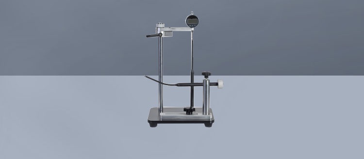
A medicine bottle’s wall thickness should be measured at defined positions around the body, shoulder and base, with additional checks at features where manufacturing or bottle geometry could produce local thinning. A single reading on the straight sidewall does not establish whether the rest of the container meets its specification.
Use a documented measurement map and compare each reading with the applicable drawing, test method or approved specification. A Wall Thickness Tester For Medicinal Bottles can provide repeatable results when its probe, access method and positioning are suitable for the bottle. The locations matter as much as the instrument: readings taken at different heights or angles cannot be compared reliably as if they came from the same point.
Where to measure on the bottle body
The body is the most accessible part of many medicine bottles, but it should not be treated as a single measurement location. Material distribution can vary both around the circumference and along the height of the container.
For a round bottle, a practical starting map uses several evenly spaced positions around the body, measured at the same height. Four positions at approximately 90-degree intervals provide a simple, repeatable pattern for an initial assessment. This is an example, not a universal sampling requirement: the approved specification or test method takes precedence and may prescribe more positions.
Repeat the circumferential checks at more than one height when the design or test purpose calls for it. Useful levels include the upper body below the shoulder transition, the middle of the straight sidewall, and the lower body above the base transition. The exact distances should be defined on the bottle drawing or measurement worksheet rather than estimated by eye.
On an oval or rectangular bottle, equal angular spacing alone may miss features that affect thickness. Include positions on the broad and narrow faces, and consider the corners or radii separately if the probe can measure them reliably. Avoid treating a flat-panel reading as representative of a nearby corner: the two areas may experience different material distribution during forming.
Record a fixed orientation reference, such as a designated mould feature or other identifiable mark. This makes it possible to return to the same locations on another bottle and investigate whether a low reading recurs in the same orientation. The reference should not itself interfere with the measurement.
Shoulder and transition areas
The shoulder connects the body to the neck and changes both slope and curvature. On bottles formed by stretching or blowing, this region deserves attention because material has to distribute across a changing shape. A shoulder measurement is especially useful when the bottle tapers sharply or when a low reading has been found near the upper body.
Select points at defined positions around the shoulder and at a specified distance from a reference feature. For a consistent map, distinguish the shoulder itself from the upper body and from the neck. A reading taken on the curved transition should not be labelled simply “body,” because a small shift in probe position can move the measurement into a different region.
The shoulder can also be difficult to measure correctly. With contact methods, the probe must be able to contact the intended surfaces as required by the instrument method without rocking, slipping or bridging a tight curve. Where the measurement principle depends on probe alignment, follow the instrument instructions for the required orientation. If the probe tip is too large for the local curvature, the display may be stable but still fail to represent the thickness at the intended point.
Where a non-destructive probe cannot reach or seat properly, a different validated method may be needed. A cut section can expose the wall for a suitable measuring instrument, but sectioning changes the sample and must be performed without distorting the surface or removing material at the measurement point. Mark the location before cutting so that the result remains traceable to the bottle map.
Base, heel and bottom panel
The base is not one uniform surface. A measurement plan may need to distinguish the lower sidewall, the heel where the wall turns into the bottom, the standing surface and the central bottom panel. Each has a different geometry, so a result from the centre of the bottom cannot automatically be used to represent the heel.
For a round bottle, checks around the heel can reveal circumferential variation near the body-to-base transition. On a bottle with corners, add relevant positions near the corner transitions where the geometry permits a valid reading. The standing ring, recessed bottom and central mould features should be identified separately if they are included in the specification.
Access is often the limiting factor. A contact gauge may reach the centre of an open bottle but not the inside of a narrow heel. A magnetic or other non-destructive system may offer another route, subject to its stated measurement range, probe geometry and suitability for the material. Neither a stable reading nor a convenient position proves that the instrument is measuring the intended local thickness.
Do not assume that the lowest point on the outside corresponds to the thinnest wall. The inside and outside contours may differ, particularly around a recessed base. If the result is critical and the geometry is difficult, use an approved sectioning method or another qualified technique to establish what the reading represents.
Neck and finish: measure only with a suitable method
The neck and finish may be important to bottle performance, but they are not interchangeable with the body wall for measurement purposes. Threads, sealing surfaces, tamper-evident features and internal contours make it difficult to identify two corresponding surfaces for a simple thickness reading.
Where the specification requires neck or finish thickness, identify the exact section and measurement direction. A probe placed across a thread crest may produce a different value from one placed in a thread root, and neither value should be reported as a general neck-wall thickness without a defined method. Some finish requirements are expressed as dimensional checks rather than wall-thickness checks; use the specified measurement for the feature in question.
Building a repeatable measurement map
A useful map identifies the bottle region, vertical position, circumferential position and orientation reference for every reading. It also states which points are mandatory for acceptance and which are additional investigative points. That distinction prevents an exploratory reading from being confused with a prescribed acceptance location, while ensuring that a concerning result is not ignored.
For example, a simple development map for a round bottle could include four positions around each of three body levels, several defined shoulder and heel positions, and a bottom-panel reading where access permits. The number and placement of points should then be adjusted to the bottle design, the test objective and the applicable specification. This example is not a claim that the pattern will locate the minimum thickness on every bottle.
When establishing or reviewing a map, consider the following:
- Bottle shape: Include flat faces, corners, asymmetric features and sharp transitions where relevant.
- Manufacturing process: Consider where the forming process and material distribution could create local variation, without assuming a particular location is always the thinnest.
- Known quality concerns: Add an investigation point when an approved drawing, previous recorded results or a specific defect indicates an area of interest.
- Measurement access: Confirm that the selected probe can reach each point and provide a valid reading on that geometry.
- Acceptance criteria: Identify whether limits apply to individual locations, a specified minimum, or another measure defined by the approved method.
A map designed to monitor consistency is not necessarily sufficient to find the absolute minimum thickness. Discrete points leave unmeasured areas between them. If the requirement is to locate a minimum over a region, the method must specify an appropriate search or scanning procedure and establish that the instrument can detect the relevant local variation.
Getting a reliable reading at the selected point
Before testing, confirm the instrument is within its required calibration or verification status and perform the checks specified by the manufacturer and the site procedure. Verification pieces should be appropriate to the instrument’s working range and intended use. A check at a thickness far from the expected bottle reading does not by itself demonstrate performance at the point of use.
Prepare the bottle according to the approved method. If it is supposed to be empty and clean, remove contents or residue that could affect contact or the measurement signal. Handle the sample consistently and allow it to reach the conditions required by the procedure. Thin plastic walls can deform under excessive contact force; the instrument and technique should avoid compressing the area being measured.
Place the probe at the marked location and allow the reading to stabilize as instructed for the device. Do not slide across a curved transition while recording a value as if it represents a fixed point. If the instrument uses a target or internal component, confirm that it is correctly positioned opposite the probe and is suitable for the bottle opening and local geometry.
For a questionable value, check the position, contact and instrument setup before deciding what it means. Repeating the reading at the same point can help distinguish positioning variation from a persistent low result, but a repeat must not be used simply to replace an unfavourable measurement. Record repeats and follow the site’s procedure for investigation and disposition.
Results should retain their location labels. A minimum value without the corresponding bottle region is less useful for diagnosing material distribution, while an average can conceal a local thin area. Keep the individual readings, sample identification, method and instrument identification, along with any deviations or limitations required by the quality system.
Interpreting differences between bottles
To compare bottles from different samples, use the same map, reference orientation and measurement method. If the bottle design, probe, method or measurement point changes, an apparent shift in thickness may reflect the change in technique rather than a change in the container. Document such changes before comparing results.
For plastic bottles, non-destructive measurements can preserve the container for additional checks, provided the instrument is qualified for the material and geometry. For glass bottles, method selection must likewise account for the instrument principle, curvature and access; a technique suitable for a plastic bottle should not automatically be assumed suitable for glass. In either case, sectioning may be necessary for inaccessible areas or for a closer examination of local geometry.
The appropriate result is the one obtained at a defined, valid location and evaluated against the requirement that applies to that location. If the specification gives no limit for an exploratory point, the reading can still support an investigation, but it should not be assigned an invented pass-or-fail threshold. Where a required location cannot be measured reliably, report the limitation and resolve the method before releasing a result as complete.
Leave A Reply
Search by Keywords