




Recent Posts
 Choosing a WVTR tester for low-permeability building membranesNov 12, 2026
 How is water vapor transmission measured in building membranes?Nov 12, 2026
 How to test building membrane WVTR under ASTM E96/E96MNov 12, 2026
 ASTM D3985 vs ISO 15105-2: Oxygen Transmission Testing for FilmsNov 12, 2026
 What Does an Oxygen Permeability Tester Measure in Barrier Films?Nov 12, 2026
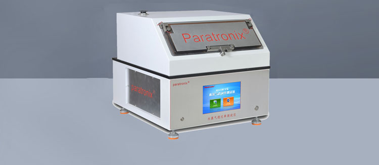
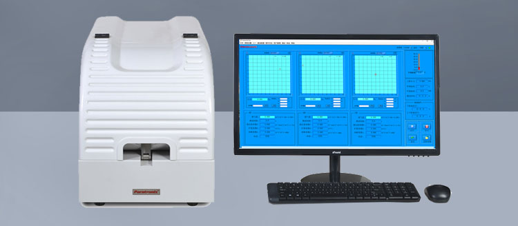
For low-permeability building membranes, the best water vapor transmission rate tester is the one that can distinguish the material’s expected transmission from the measurement system’s background under the conditions the product specification requires. A low advertised detection limit is a useful starting point, but it does not establish that the complete test—including sealing, conditioning and endpoint selection—will produce a dependable result.
Start by identifying the decision the result must support. A laboratory comparing development formulations may value controlled conditions and sensitivity to small differences. A manufacturer releasing production batches may place greater weight on repeatability, throughput and agreement with a specified reference method. Those priorities can lead to different equipment choices even when the material is the same.
Define the result you need before comparing instruments
Collect the material specification, the required test method and any customer reporting requirements before reviewing instrument brochures. Establish the expected range of water vapor transmission rates, the decision limit and the temperature and humidity conditions at which the limit applies. If the expected rate is unknown, representative samples tested by a suitable laboratory can provide a starting point for equipment evaluation.
Pay attention to how the requirement is expressed. Water vapor transmission rate is commonly reported as mass passing through a defined area over time, such as g/(m²·day). Permeance and vapor resistance describe related properties but use different expressions and units. A result expressed as water vapor resistance or an equivalent air layer thickness may require a method-specific calculation. Request the quantities and units needed in the final report before deciding whether the instrument’s software and method can deliver them.
Thickness also matters. If the specification concerns a finished membrane, evaluate specimens at the intended product thickness rather than assuming that data for a thinner film will represent the finished material. For multilayer products, record the construction and which face is exposed to the higher humidity. Some materials may respond differently when their orientation or moisture history changes.
The operating point should sit comfortably within the tester’s demonstrated capability. If the acceptance threshold lies close to the lower end of the measuring range, small background effects may consume a large share of the result. Ask the supplier to explain the detection limit, quantification limit and uncertainty under the proposed test conditions, including how those figures were established. A display that shows extra decimal places does not establish that those digits are meaningful.
Choose a method that answers the same question as the specification
Two broad approaches are relevant when evaluating low-permeability membranes: gravimetric cup methods and instrumented methods that measure water vapor passing into a controlled receiving environment. Both can be useful, but their results should be compared only after the test conditions and procedure have been examined.
In a gravimetric test, a specimen seals the opening of a cup, and the change in cup mass over time is used to calculate transmission. Cup methods can be appropriate for building products and are referenced by established standards, including ASTM E96/E96M and ISO 12572. The applicable procedure may specify different humidity conditions, cup arrangements, conditioning and calculations. Select the edition and procedure called for by the product specification or customer; citing a standard number alone does not establish equivalence between two tests.
For a very resistant membrane, mass change may be small relative to balance resolution, changes in the cup assembly or losses at the seal. A longer test can improve the amount of measurable mass change, but it also increases the time during which temperature variation, handling and seal integrity must remain controlled. Ask whether the laboratory has the balance, environmental control and repeatable weighing procedure needed for the expected rate, rather than treating the cup as a stand-alone accessory.
Instrumented permeation systems use a controlled humidity difference across the specimen and measure vapor reaching the receiving side, often with a sensor. ASTM F1249, for example, describes an infrared sensor method for certain films and sheeting. Sensor-based equipment can provide continuous data and controlled conditions, but the suitability of a particular instrument depends on its sensor, fixture, operating range and applicable method. A system designed for packaging films should be evaluated carefully with thicker, textured or composite building membranes.
Neither approach automatically reproduces the other. A cup test and a sensor test can impose different humidity gradients and expose different aspects of the specimen to the test environment. Moisture-sensitive materials may produce different values under different conditions even when both tests are performed correctly. If a customer requires a particular method, use that method for acceptance unless an alternative has been agreed. If an instrumented method is being considered as a faster internal screen, establish its relationship to the reference method using representative materials across the expected production range.
Examine the whole measurement system at the low end
Low-permeability testing magnifies effects that may be negligible for more permeable materials. The evaluator should therefore ask for evidence from the complete test arrangement, not just the sensor specification.
Background and leakage. Vapor can enter through seals, fittings or other parts of a test assembly. Background may also arise from moisture released by components after a change in conditions. Ask how the instrument establishes its blank or background, how frequently that check is needed and how the result is used. A background correction is more credible when it is small and stable relative to the expected specimen signal. If it is similar in size to the signal, the corrected result may be too uncertain for a tight acceptance decision.
Seal and exposed area. Building membranes can have embossing, reinforcement, coatings or uneven edges that make sealing harder than it is for a smooth film. A leak around the specimen can be mistaken for transmission through it. Review the fixture geometry, gasket material, clamping method and maximum specimen thickness. Ask whether the supplier can test the actual construction and demonstrate a practical leak-check procedure. The exposed area used in the calculation must also match the area defined by the fixture and seal.
Conditioning and steady state. A membrane may absorb moisture before transmission reaches a stable regime. Initial readings can therefore reflect changes in moisture stored in the specimen as well as passage through it. The required conditioning and endpoint depend on the material and method. Ask how the equipment displays the time history, what rule determines the reported result and whether the operator can inspect the underlying data. A short test time is attractive only if it supports a defensible endpoint for the material being tested.
Humidity and temperature control. The driving force across a membrane depends on the conditions on both sides. Small deviations can matter when results are close to a specification limit, and moisture-sensitive layers may change behavior at different humidity levels. Check the controlled range and stability at the actual setpoints, including the receiving side. A broad operating range does not by itself show that the system controls the required point accurately.
Test the proposed workflow with representative membranes
A specification sheet narrows the field; a sample evaluation shows whether the equipment fits the application. Provide specimens that represent the finished product, including its normal thickness, surface texture and layer structure. If the portfolio includes several constructions, select samples that challenge the fixture and cover the expected range of transmission rates.
Before the evaluation, agree on the test conditions, specimen orientation, conditioning, number of specimens and endpoint. Request individual results and time histories as well as the reported average. Repeat measurements should be considered alongside the intended decision: variation that is acceptable for distinguishing two development materials may be too large for releasing batches close to a limit.
When an established method is already used for acceptance, compare the proposed system against it under documented conditions. Agreement on one sample does not prove agreement across a product family. Differences may arise from the humidity gradient, specimen preparation, thickness, orientation or endpoint, as well as from instrument performance. Investigate the pattern before applying a conversion or changing an acceptance limit.
Throughput should be evaluated at the same time. The relevant figure is the elapsed time needed to condition, mount, test, remove and document the required specimens, including any repeat tests and background checks. Multiple test positions can improve capacity, but their value depends on whether each position meets the required sensitivity and whether samples can reach an acceptable endpoint within the production schedule.
For routine quality control, also assess the work needed to keep results comparable over time: calibration or verification, checks of seals and fixtures, maintenance of humidity control and retention of raw data. A system with an impressive low-end specification can be difficult to use if its verification procedure is impractical for the laboratory.
The final choice should follow the decision limit. If the selected method, specimen fixture and demonstrated uncertainty allow samples on either side of that limit to be distinguished reliably, the tester has a sound basis for the application. If they do not, reconsider the method, test conditions or role of the instrument before relying on its output for acceptance.
Leave A Reply
Search by Keywords