




Recent Posts
 What does ASTM F1249 require for medical packaging WVTR testing?Nov 13, 2026
 Infrared vs Gravimetric WVTR Testing for Food PackagingNov 13, 2026
 ASTM F1249 and ASTM E96: Choosing a WVTR Test Method for Food FilmsNov 13, 2026
 What does a WVTR tester measure in pharmaceutical containers?Nov 13, 2026
 ASTM F1249 and E96: WVTR Test Standards for Biodegradable FilmsNov 13, 2026
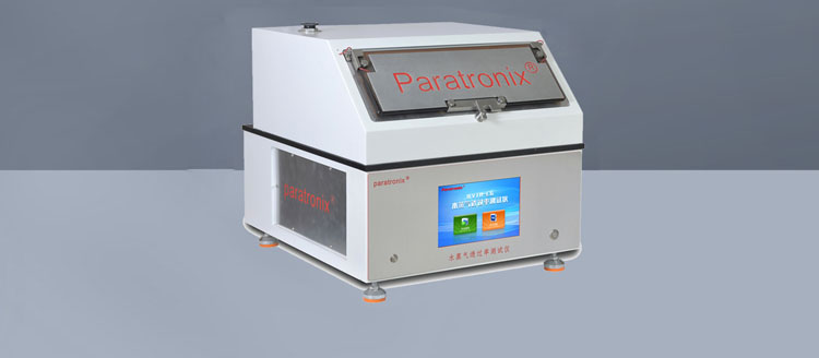
Building membranes help manage moisture in walls and roofs, but their appearance rarely reveals how much water vapor they allow through. Two sheets that look almost identical may behave very differently once installed. To compare them, manufacturers and specifiers need measurements taken under defined conditions—not simply descriptions such as “breathable” or “vapor resistant.”
A water vapor transmission rate tester for building membranes measures how quickly vapor passes through a specimen when there is a difference in humidity across it. The result can help characterize a material, check production consistency, or support product selection. Understanding the test method is just as important as reading the number: temperature, humidity, specimen preparation, and the way results are expressed all affect the comparison.
What does water vapor transmission measure?
Water vapor transmission is the movement of water molecules in their gaseous state through a material. It is different from liquid water penetration. A membrane may resist rainwater while still allowing a certain amount of water vapor to pass through it. Conversely, a vapor-control layer may be designed to greatly restrict vapor movement.
The water vapor transmission rate, often abbreviated to WVTR, describes the mass of vapor passing through a specified area over a specified time under stated conditions. It is commonly reported in grams per square meter per 24 hours, written as g/m²·24 h.
A higher WVTR generally indicates that more vapor passes through the tested specimen under those conditions. It does not automatically mean that the membrane is better. A roof underlay and an interior vapor-control layer can serve different purposes, so the appropriate performance depends on the assembly, climate, and moisture-management strategy.
The cup method: measuring vapor by a change in mass
One widely used approach places a membrane specimen over the open mouth of a test cup. The specimen is sealed around its edges, separating the environment inside the cup from the controlled atmosphere outside it. Because the humidity differs on the two sides, water vapor moves through the exposed area of the membrane.
The cup is weighed at intervals. Its change in mass, once a suitable steady rate has been established, is used to calculate vapor transmission. Depending on the arrangement, the cup may gain or lose mass.
Desiccant cup and water cup arrangements
In a desiccant cup, a drying agent creates a relatively dry environment beneath the specimen. When the surrounding chamber is more humid, vapor tends to move into the cup, producing a mass gain. This is often called the dry-cup method.
In a water cup, water or another specified humidity source creates a more humid environment inside the cup. Vapor generally moves outward toward the drier controlled atmosphere, producing a mass loss. This is often called the wet-cup method.
These arrangements should not be treated as interchangeable. Some membrane materials respond to humidity, so dry-cup and wet-cup tests can give different results for the same product. Each result describes performance under its particular test conditions; neither is a universal number for every building situation.
From weighing data to WVTR
The basic calculation divides the steady mass change per unit time by the exposed test area:
WVTR = mass change ÷ (exposed area × time)
For example, if a specimen has an exposed area of 0.01 m² and the cup changes mass at a steady rate of 0.02 g over 24 hours, the calculated WVTR is 2 g/m²·24 h. This simplified example illustrates the arithmetic; an actual test must also follow the selected standard’s requirements for conditioning, weighing intervals, calculation, and reporting.
Small measurement errors can matter, particularly for materials with low vapor transmission. Edge leakage, inaccurate exposed-area measurements, changes in cup temperature, or handling that affects the balance reading can all distort the result. A carefully sealed specimen and a stable test environment are therefore central to a useful measurement.
Can an instrument measure vapor transmission without weighing cups?
Yes. Instrumental methods can measure vapor passing through a specimen using a humidity sensor or another detection system. In a typical arrangement, the membrane separates a humid side from a drier side. The instrument controls or monitors the relevant conditions and detects vapor reaching the receiving side.
Depending on the method and equipment, a carrier gas may transport the transmitted vapor to a sensor. The instrument uses the measured vapor signal, exposed area, and test conditions to calculate a transmission result. Such systems can reduce routine manual weighing and provide a record of changing readings as the test progresses.
That does not make every sensor-based result directly equivalent to a cup-method result. The humidity gradient, temperature, specimen mounting, measurement principle, and applicable procedure may differ. When comparing data from different instruments, check whether the methods and conditions are compatible before attributing a difference to the materials themselves.
The choice also depends on the membrane. Some building products are textured, multilayered, reinforced, or relatively thick. A test fixture must hold the specimen securely and seal its edges without damaging it or creating a bypass path for vapor.
Standards used for building membrane testing
Test standards give laboratories a common framework for specimen preparation, conditioning, measurement, and reporting. Relevant documents include:
- ASTM E96/E96M: Covers water vapor transmission of materials using desiccant and water methods. It is widely referenced for construction materials, including membranes and sheets, where applicable.
- ISO 12572: Addresses the determination of water vapor transmission properties of building materials and products using cup-based procedures.
- EN 1931: Addresses water vapor transmission properties of flexible sheets for waterproofing, including plastic and rubber sheets for roof waterproofing and other specified flexible sheet products.
The applicable edition, product specification, and test arrangement matter. A standard may offer more than one set of conditions or require particular calculations and reporting details. Before commissioning a test, confirm that the chosen method is appropriate for the material and for the market or specification in which the result will be used.
Instrumental methods may be covered by other standards or agreed procedures. A statement that an instrument measures WVTR does not, by itself, establish compliance with a particular building-material standard.
WVTR, permeance, and Sd value: why the numbers look different
Datasheets do not always express vapor behavior in the same way. Alongside WVTR, you may encounter water vapor permeance, permeability, vapor diffusion resistance factor, or an equivalent air layer thickness known as the Sd value.
WVTR describes the measured mass flow per area and time under stated conditions. Permeance relates vapor flow to the vapor pressure difference across the specimen. Permeability also accounts for material thickness and is generally more meaningful for a homogeneous material than for a complex multilayer membrane.
The Sd value expresses the vapor diffusion resistance of a material as the thickness of a stationary air layer with equivalent resistance. A lower Sd value generally indicates lower resistance to vapor diffusion; a higher value indicates greater resistance. It is not simply another label for WVTR.
Converting between reported properties requires the correct pressure difference, units, and relevant calculation assumptions. For this reason, comparing a WVTR value on one datasheet with an Sd value on another without further information can lead to the wrong conclusion.
What changes a test result?
A membrane does not necessarily transmit vapor at the same rate in every environment. When reviewing results, pay attention to the conditions behind the figure.
- Temperature: It affects vapor pressure and can influence the behavior of the membrane itself. Results obtained at different temperatures may not be directly comparable.
- Relative humidity: The humidity on each side establishes the driving force for vapor movement. Some materials are also sensitive to the humidity level, not just the difference between sides.
- Specimen condition: Conditioning time, aging, damage, and previous exposure can affect the material being tested.
- Orientation: Multilayer or coated membranes may be direction-sensitive. The report should identify which face was exposed to each environment where relevant.
- Mounting and sealing: A leak around the specimen can be mistaken for transmission through it. Wrinkles, punctures, and an incorrectly defined test area can also affect results.
- Air movement and boundary layers: Conditions near the specimen surface can influence the measured transfer, particularly when the material allows vapor to pass relatively readily.
Sampling deserves attention too. If a membrane has reinforcement, coatings, or visible variation across its width, a small specimen may not represent the whole roll. Follow the relevant standard and product requirements for specimen selection and replicate testing.
Reading a report with confidence
A useful report provides more than a single headline value. Look for the test standard and procedure, temperature, relative humidity on each side, specimen orientation, exposed area, conditioning details, and the units used. It should also make clear whether the result is for an individual specimen or a calculated result from several specimens.
If two products have different reported values, ask whether they were tested under matching conditions. A dry-cup result at one temperature should not be compared casually with a wet-cup result at another. Similarly, a laboratory result for an intact membrane does not describe every installed condition: seams, overlaps, penetrations, damage, and workmanship can influence moisture movement through a completed assembly.
For product development or quality control, repeat testing under a consistent method can reveal changes between batches. For design decisions, the result should be considered alongside the rest of the wall or roof build-up, including the location of the membrane and the assembly’s ability to dry.
Choosing a water vapor transmission rate tester for building membranes
Start with the question the test must answer. Is the aim to compare development samples, monitor production, or obtain data for a stated specification? The answer helps determine which standard, humidity range, temperature control, and reporting format are needed.
Then examine the practical fit. Check whether the expected transmission range is within the equipment’s measurement capability, whether the fixture can seal the membrane’s surface and thickness, and whether the test area is suitable for the material’s structure. Consider the time needed to reach a stable result, the number of samples that must be tested, and the calibration and maintenance requirements. For cup testing, balance resolution and chamber stability are also important.
Paratronix Instruments Co., Ltd. develops and supplies packaging testing instruments and testing solutions for materials used in industries including pharmaceutical packaging, plastics, and high-barrier applications. When evaluating equipment for building membranes, the sensible next step is to discuss the specimen, target method, and expected measurement range rather than assume that a tester intended for one material will suit every other application.
Water vapor transmission testing turns an otherwise invisible property into useful evidence. The strongest comparison is not simply between two numbers, but between results whose methods, conditions, and intended uses are understood.
Leave A Reply
Search by Keywords