




Recent Posts
 How Does a Combination Cap Puncture Tester Work?Nov 02, 2026
 How to assess a Luer separation force tester against ISO 80369-20Nov 02, 2026
 What does ISO 80369-7 require for Luer lock unscrewing tests?Nov 02, 2026
 What does a Luer taper ease of assembly tester measure?Oct 31, 2026
 What does ISO 80369-7 require for Luer ease of assembly tests?Oct 31, 2026
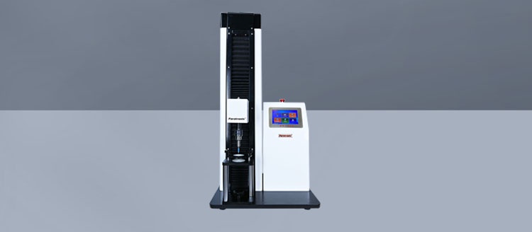
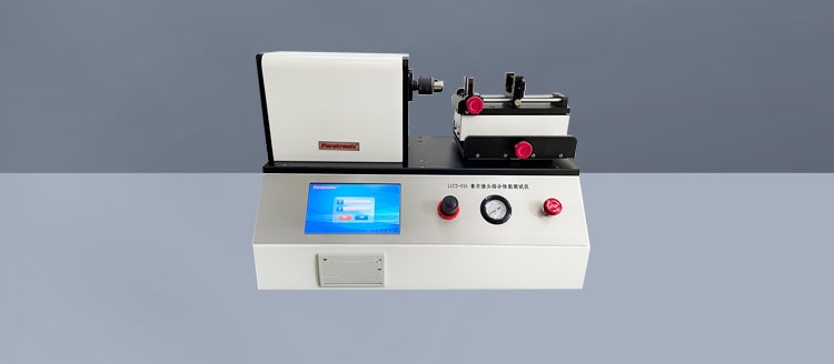
A combination cap puncture tester measures the force needed for a defined probe to penetrate the intended access area of a cap or closure. It does this by moving the probe against a secured specimen at a controlled speed while recording force. The result helps determine whether puncture resistance is consistent under the specified test conditions.
The measurement is not, by itself, proof that a package will remain sterile or leak-free. A useful assessment connects puncture force with the closure design, the intended spike or access device, and separate tests for other performance requirements.
What happens when the probe meets the cap?
The tester converts a mechanical interaction into a force measurement. A drive mechanism moves a probe and the specimen relative to one another. As the probe contacts the cap, the closure resists deformation; the force sensor records that resistance as penetration proceeds. Depending on the instrument and method, the system displays a peak force, a force-versus-displacement curve, or both.
A combination cap can include multiple components or material layers, such as a protective outer element and an elastomeric sealing area. The exact construction varies. A meaningful test therefore begins by identifying which part of the closure is intended to be pierced and which components should be present when the measurement is made. Testing an exposed sealing area is not equivalent to driving a probe through a protective component that would normally be removed before use.
The force response reflects more than a simple “breakthrough” event. The cap can compress and deform before the probe enters. Resistance may change as the tip cuts or separates the material and as the probe shaft moves through the opening. If the closure has several layers, the curve may show more than one rise or change in slope. These features can be informative, but they should not automatically be assigned to particular layers without supporting evidence from the specimen design and test observations.
Results are commonly reported in newtons. The maximum recorded force is often used as the puncture force, but the method must define the portion of the test over which that maximum is taken. A peak generated after the probe has already passed through the relevant material, for example by contacting a fixture or another component, should not be mistaken for the force required to pierce the intended access area.
The components that control the measurement
A puncture tester is more than a force gauge with a sharp tip. Its measurement depends on a coordinated set of components:
- Probe or puncture tool: Its tip geometry, diameter, material and surface condition affect how the closure deforms and penetrates. A test using one probe design cannot automatically represent another access device.
- Force sensor: The load cell measures the resistance transmitted through the probe or fixture. Its capacity and verified measuring range should suit the forces expected, including any possible peaks.
- Drive mechanism: The crosshead or actuator controls relative movement and test speed. Excessive vibration, backlash or unstable movement can affect the recorded response.
- Specimen fixture: The fixture holds and supports the cap or assembled package while allowing the probe to reach the intended puncture location without interference.
- Control and recording system: The software or display sets test parameters and records results. Where force-displacement curves are needed, data acquisition must be sufficient to capture the relevant peak.
These elements work as a system. A calibrated load cell cannot compensate for a slipping specimen, a damaged probe or a fixture that supports the cap differently from the defined method. Likewise, a high displayed resolution does not establish that the complete measurement is accurate.
From specimen preparation to a recorded result
A repeatable test starts with a written method that defines the specimen and its condition. This includes the cap configuration, whether it is tested on its container or in a representative holder, and any conditioning or preparation required before measurement. If a protective cover is removed in normal use, the method should state whether and how it is removed for the test.
The specimen is then positioned in the fixture so that the target area is aligned with the probe. The support beneath and around the closure matters: a loosely supported cap can bend, while a rigidly supported one can respond differently. Both arrangements may be useful for different purposes, but their results should not be treated as interchangeable.
Before testing, the operator checks the probe, fixture and force indication according to the instrument procedure. The probe is brought toward the specified starting position, and the force measurement is zeroed or otherwise initialized as required by the method. The system then moves at the specified speed until the prescribed travel, penetration depth or other stopping condition is reached.
The instrument records the force response during the movement. The reported value might be the maximum force during the defined puncture interval; a method may also retain the curve and other observations. Afterward, the specimen can be inspected for visible anomalies, such as an off-center puncture or movement in the fixture. A single damaged or mispositioned specimen can produce a misleading result, so invalidation criteria should be established before testing rather than chosen after an unfavorable reading.
Each specimen generally provides one destructive puncture result at a given location. Repeated punctures in the same area are not equivalent to tests on untouched specimens because the first penetration alters the material. If repeated access is relevant to use, it needs a separate, explicitly defined procedure.
Why test conditions change the measured force
Probe geometry is central to comparability. A sharp, narrow tip can initiate penetration differently from a blunt or broader one. Shaft diameter and surface finish can also influence the force after the tip enters. When the purpose is to evaluate a specific spike or access device, the test probe should represent the relevant geometry as closely as the method requires. If a standard test probe is used for process control instead, the result should be interpreted as resistance to that probe—not as a direct measurement of every possible device.
Speed affects the material response. Elastomeric and polymeric components can behave differently when deformed at different rates. A faster test can also change how sharply a peak appears in the recorded data. Test speed should therefore be fixed in the method and included with the result. Two peak-force values obtained at different speeds may not indicate a genuine difference in closure quality.
Alignment and location affect the puncture path. An angled probe may contact a larger or different area of the closure than an aligned probe. An off-center location can encounter a different thickness or underlying support. The method should specify the target location and orientation, while the fixture should make those settings practical to reproduce.
Conditioning and product configuration matter. Temperature, storage history and specimen preparation can influence material behavior. An assembled closure may also respond differently from a loose cap because the container and retention system affect support. When comparing batches or suppliers, the same preparation and conditioning should be applied, or the differences should be documented and evaluated.
Travel and stopping conditions affect what the peak represents. A shallow test may capture initial penetration but miss resistance encountered deeper in the closure. Excess travel can introduce contact with the holder or another package component. The chosen endpoint should cover the intended puncture event without introducing unrelated contact.
Reading the force curve without overinterpreting it
A peak value is convenient for comparison, but it compresses the entire puncture event into one number. Two specimens can have similar maximum forces and different curves: one may show a gradual increase followed by a clear drop, while another may show several smaller resistance changes before reaching its maximum. Viewing the curve can help identify unusual behavior, fixture contact or variation that a single number conceals.
Displacement also needs careful interpretation. The tester records relative movement of its moving parts; that movement is not necessarily equal to the depth of the probe inside the closure. Deformation of the specimen and compliance in the test setup can contribute. If penetration depth is a critical output, the method must define how it is established rather than assuming that crosshead travel alone represents the depth within the material.
Sample results should be evaluated as a set, using a justified sample size and predefined acceptance criteria where applicable. The average can show the general level of resistance, while the spread and individual high values can reveal inconsistency. A low average does not rule out occasional difficult-to-puncture closures, and one high value should be investigated in the context of the specimen and test setup before a cause is assigned.
Force limits cannot be selected responsibly from the instrument reading alone. They depend on the closure, the intended access device, the use scenario and the applicable product requirements. An easier puncture is not automatically a better outcome if a material or design change compromises another necessary property.
How puncture testing fits into packaging quality control
Within a controlled method, puncture results can support comparison of incoming materials, production lots or proposed design changes. An unexpected shift in force may prompt checks of material formulation, closure dimensions, assembly conditions or test equipment. The measurement identifies a change in mechanical response; it does not by itself establish which manufacturing variable caused that change.
It is also important to distinguish puncture resistance from package integrity. A closure may be easy to penetrate yet fail another requirement, or it may provide a satisfactory barrier while requiring excessive force for the intended access device. Puncture testing does not establish container-closure integrity, sterility, resealing performance after access or the absence of particulate generation. Those questions require suitable, separate evaluations where relevant.
Traceability makes the force result useful beyond the immediate test. A report should identify the specimen and configuration, probe, fixture, puncture location, speed, endpoint, conditioning, individual results and any deviations or anomalies. It should also identify the method used, including the edition or internal revision where applicable. Applicable specifications and standards depend on the product and intended use; the tester itself does not confer compliance.
The strongest comparisons are made under the same controlled conditions, with changes to equipment or method assessed before results are combined. That discipline allows puncture force to serve its intended purpose: showing how consistently a defined closure responds to a defined penetration event.
Leave A Reply
Search by Keywords