




Recent Posts
 How to assess a Luer separation force tester against ISO 80369-20Nov 02, 2026
 What does ISO 80369-7 require for Luer lock unscrewing tests?Nov 02, 2026
 What does a Luer taper ease of assembly tester measure?Oct 31, 2026
 What does ISO 80369-7 require for Luer ease of assembly tests?Oct 31, 2026
 What Does a Luer Taper Easy Assembly Tester Measure?Oct 30, 2026
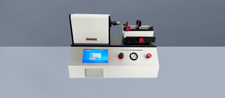
A Luer Taper separation force Tester should be assessed against the complete test method, not just its maximum load rating. The equipment must be able to hold the specified connector assembly, apply the required axial loading conditions, measure and record the relevant force, and provide evidence that those functions perform as intended under the applicable edition of ISO 80369-20.
This distinction matters when a connector appears to separate at an unexpected force. The result may reflect the connector, but it may also be affected by assembly conditions, fixture alignment, crosshead movement or force capture. A tester that cannot control or document those factors makes it difficult to distinguish a product issue from a measurement issue.
Start with the applicable method, not the instrument brochure
ISO 80369-20 contains common test methods for small-bore connectors. Its methods are used alongside the applicable connector-specific standard and the laboratory’s defined test plan. Before comparing instruments, obtain the controlled editions relevant to the connector and identify the separation or resistance-to-disconnection procedure that applies. Do not assume that every Luer configuration uses the same preparation, assembly procedure or acceptance criterion.
Translate the method into equipment requirements. Identify the specimen and mating component, any reference connector requirements, assembly conditions, loading direction, speed or rate, conditioning, endpoint and recorded result. Also identify whether the applicable connector standard specifies an acceptance limit. The test method describes how to perform a measurement; an instrument cannot determine product conformity without the correct acceptance requirements.
Ask the supplier to map each relevant requirement to a function, accessory or documented procedure. A statement such as “suitable for ISO 80369-20” is a starting point, not evidence that a particular configuration covers your connector and test conditions. Where a requirement depends on a separate fixture, software option or external device, record that dependency before evaluating the quotation.
Check how the assembly is held and pulled
The fixtures are often the deciding factor. The tester must grip the components securely while leaving the connection and its intended separation path unobstructed. Clamping on a flexible tube, for example, can introduce stretch or slippage that is not representative of separation at the connector. A fixture that bears on the locking feature can also change the way the assembly releases.
Examine the proposed setup with actual specimens or representative drawings. Confirm which surfaces are gripped, how the mating parts are supported and whether the setup accommodates the connector geometry without crushing or distorting it. Verify that the fixtures permit the relative movement required by the applicable procedure and do not unintentionally apply a bending moment or torque during axial loading.
Alignment deserves a practical demonstration. The force line should pass through the intended axis of the connection as closely as the method requires. Off-axis loading can create side forces, change the observed separation behavior and increase variation between runs. Ask how alignment is established and maintained when fixtures are changed, and whether operators can reproduce the same position without relying on visual judgment alone.
For threaded or locking designs, distinguish the action being measured from other possible failure modes. An axial separation test is not automatically a substitute for a torque-based disconnection test. Confirm that the fixture arrangement and reported endpoint correspond to the procedure being claimed, rather than simply pulling until some part of the assembly fails.
Evaluate the force measurement across the working range
A large force capacity does not by itself make a tester suitable. Compare the expected test forces and any applicable limit with the calibrated range of the load cell, the stated measurement uncertainty or accuracy, and the displayed and recorded resolution. A high-capacity cell may be poorly matched to a low-force test, while an undersized cell can overload during setup or an unexpected failure.
Request a calibration certificate for the installed measurement chain, including the load cell and instrument indication where applicable. Check the calibration points, range, traceability and validity against the laboratory’s own calibration system. Manufacturer specifications describe claimed performance; calibration evidence shows how the particular instrument performed at the tested points. Neither automatically proves performance at every untested force or during a dynamic separation event.
The tester must also capture the result defined by the method. If the procedure requires a peak force, ask how peak detection works, what sampling or acquisition settings are available and whether raw force-versus-time or force-versus-displacement data can be retained. A display that updates slowly may show a plausible value while missing a short force peak. The supplier should explain the acquisition capability and demonstrate that it is appropriate for the loading conditions used.
Zeroing and tare functions should be clear and controlled. Operators need to know whether fixture weight, preload or contact force has been removed from the indication, and at what stage zeroing occurs. An undocumented preload can alter both the starting condition and the reported maximum.
Confirm that motion controls reproduce the procedure
Inspect the settings available for crosshead speed or other required loading control, travel, stopping conditions and return movement. The relevant standard may specify a particular loading condition; the tester must be able to set and maintain it within the applicable requirements, not merely display a nominal value. Request evidence of speed verification over the range to be used, including the test setup where feasible.
Also check the available travel with the fixtures and specimen installed. It must cover positioning, the required test movement and the expected separation without reaching a mechanical limit. Excess travel can create a safety hazard after release, so consider adjustable limits, guarded moving parts and a stop function appropriate to the equipment and laboratory environment.
Some procedures depend on how the connection was assembled before the pull. A separation result may be influenced by assembly force, torque, relative rotation or timing. Determine which of these conditions the applicable method specifies and how they will be controlled. The separation tester might perform part of the assembly, but a separate calibrated device or a documented manual procedure may be necessary. Do not credit a pull tester with controlling assembly conditions unless that capability is actually supplied and verified.
Ask for a representative demonstration
A useful demonstration follows the planned workflow rather than using an unrelated sample to show that the crosshead moves. Provide the supplier with the relevant connector dimensions, intended mating component and method requirements. Where specimens can be shared, observe whether the proposed fixture can be installed without improvised packing, excessive tightening or contact with the feature under test.
- Review setup: identify the fixture, load cell, specimen orientation and method settings used.
- Observe assembly and loading: check how the initial connection is made, how alignment is established and when force is zeroed.
- Inspect the measurement: confirm that the required loading condition is applied and that the event and endpoint are captured.
- Examine the output: check whether the report identifies the test configuration, result, units and any relevant exceptions.
- Repeat the setup: remove and reinstall the specimen or fixture to see whether positioning depends on undocumented operator adjustments.
A demonstration is useful evidence of suitability, but it is not a substitute for installation, calibration or method validation in the receiving laboratory. It should also expose limitations: a fixture that works with one connector size may not securely hold another, and a method file configured for one test condition may not cover a different connector standard.
Separate equipment evidence from product conformity
Documentation should allow a reviewer to reconstruct what was tested and how. At a minimum, assess whether the system or associated records can capture specimen identification, relevant connector and mating-component details, method and edition, fixture configuration, test settings, date, force result and units. Where the procedure requires conditioning or a specific assembly process, those records may be maintained outside the instrument but must remain linked to the result.
Check whether test settings can be reviewed after a run and whether changes to a method are identifiable. If electronic records are used in a controlled quality system, assess access controls, data export, retention and audit-trail functions against the organization’s own requirements. A PDF report alone does not establish that settings were protected or that raw data can be retrieved.
Be precise about claims. Calibration supports measurement traceability; equipment verification shows that specified functions operate as intended; method validation or verification addresses suitability for the laboratory’s use. None of these, by itself, certifies that every connector tested conforms to ISO requirements. Product conformity depends on the applicable standard, representative samples, correct execution and comparison with the specified acceptance criteria.
When results look inconsistent
Before changing acceptance limits or rejecting a batch, compare the test records for differences in specimen preparation, mating component, assembly conditions, fixture position and loading settings. Look at the force trace as well as the reported maximum: an early irregular event may indicate slip in a grip, contact with a fixture or another setup issue rather than separation at the intended interface. The trace alone may not identify the cause, so inspect the specimen and fixture after the test.
If the discrepancy persists, verify the force indication and motion settings, inspect the fixture for wear or looseness, and repeat the evaluation under controlled conditions using the same documented procedure. Preserve the original results and record any changes. Where equipment behavior remains unexplained, remove the affected configuration from routine decisions until its suitability has been established; do not treat a convenient repeat result as proof that the first setup was valid.
Leave A Reply
Search by Keywords