




Recent Posts
 Heat Seal Tester vs Hot Tack Tester: Which ASTM Standards Apply?Oct 24, 2026
 Gas Permeability Testing: Differential or Equal Pressure?Oct 24, 2026
 ISO 9187 and Ampoule Break Force Testing: Which Requirements Apply?Oct 24, 2026
 What does a syringe needle puncture tester measure during insertion?Oct 24, 2026
 What does ASTM F543 require of a bone screw torque tester?Oct 23, 2026

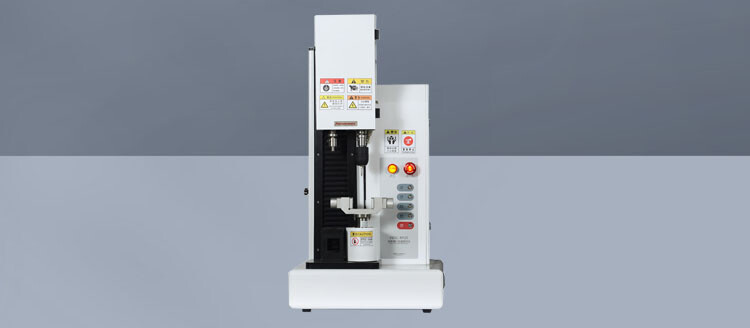
The ISO 9187 requirements relevant to an ampoule break force test come from the applicable part, edition, ampoule design, and referenced test method. ISO 9187-1 covers glass ampoules for injectables, while ISO 9187-2 addresses one-point-cut (OPC) ampoules. Evaluating an OPC ampoule therefore requires consideration of the relationship between these parts. A general statement that equipment is “ISO 9187 compliant” does not establish which ampoules it can test or which requirements it satisfies.
The assessment starts with the ampoule specification and the controlled standard text. These establish the required specimen geometry, breaking arrangement, test conditions, and acceptance criteria. Equipment suitability follows from those requirements: fixture dimensions, loading direction, test speed, force measurement performance, and recording capability must support the selected method.
Establish which provisions govern the ampoule
ISO 9187-1 and ISO 9187-2 have related but different scopes. The general requirements for glass ampoules and the additional provisions for OPC designs should be read together where applicable. The presence of a colored mark alone is insufficient to determine the complete testing requirement. The ampoule drawing and specification need to identify its opening system and the meaning of its markings.
For an OPC ampoule, the localized cut creates an intended fracture initiation point. Its angular position relative to the applied load affects the result. An ampoule with a circumferential breaking feature presents a different geometry. Applying an OPC orientation procedure to every ampoule, or ignoring orientation because all specimens have a marked neck, introduces an uncontrolled difference.
The edition also belongs in the test specification. A method developed against one edition should not automatically be described as satisfying a later edition without reviewing the relevant changes. Conversely, a contract referring to a particular edition needs a documented basis before a different edition replaces it.
A useful applicability record connects the following information:
- The standard part and edition named in the product specification, including applicable amendments.
- Ampoule form, nominal capacity, dimensions, and opening system, with a drawing reference where available.
- The required test method and the source of each acceptance limit.
- Any additional contractual conditions, such as testing after a specified processing stage. These remain identifiable as additional conditions rather than being attributed automatically to ISO 9187.
This record prevents a common error: selecting a force limit from one ampoule category while using the fixture arrangement or specimen definition associated with another.
Separate the test method from the acceptance requirement
The method defines how a breaking force is produced and measured. The acceptance requirement defines how that result is judged. Both are necessary, but they answer different questions. A correctly measured force does not demonstrate conformity until it has been compared with the criterion applicable to that specimen.
Where the applicable standard specifies breaking-force limits for defined ampoule categories, the relevant category must be established before testing. A value copied from a previous report or an equipment brochure is not sufficient evidence. Nominal capacity alone should not replace the other identifying features required by the applicable provisions.
Additional product limits also need clear attribution. A packaging specification might impose a narrower operating window than the referenced standard. In that situation, the report should distinguish conformity with the standard from conformity with the additional specification. Combining both into an unexplained “pass” obscures the basis of the decision.
Fixture geometry determines what the force reading means
An ampoule break force test measures the force associated with fracture under a defined mechanical arrangement. It does not measure a property independent of that arrangement. Support position and loading position establish the bending conditions at the neck. Changing their separation changes the mechanical relationship between the recorded force and the stress that initiates fracture.
Consequently, a fixture that physically accommodates an ampoule is not necessarily suitable for the applicable ISO method. Its supports, loading contact, adjustment range, and positioning references need to correspond to the required geometry. Adjustable components also need reproducible settings; an unrecorded adjustment makes comparisons between batches difficult to defend.
Contact shape matters. A worn edge, damaged support, or incorrectly seated insert changes how the glass contacts the fixture. Local damage introduced during placement can cause premature fracture, while movement during loading changes the intended force application. Fixture inspection and cleaning therefore contribute directly to measurement consistency.
For OPC designs, rotational positioning deserves particular attention. The relationship between the cut and the applied load must follow the applicable procedure. A locating feature is useful only when it references the correct ampoule feature and holds that relationship during loading. A visually convenient position is not sufficient justification.
Compatibility should therefore be demonstrated with representative ampoules covering the intended dimensional range. A demonstration using one convenient size establishes little about other neck profiles, body diameters, or opening systems.
Force capacity alone does not establish measurement suitability
The load cell must accommodate the expected breaking forces without overload while retaining adequate performance in the working range. A high maximum capacity offers little value if measurement uncertainty at the forces of interest prevents a reliable conformity decision.
Display resolution, force accuracy, and measurement uncertainty describe different things. A display with many decimal places does not establish that the complete system measures to that precision. Calibration evidence needs to address the relevant force range, and the equipment configuration used for testing must be represented appropriately.
The fracture event also places demands on data capture. Once the neck breaks, the load falls rapidly. The indicated peak depends on the response of the measurement chain, including acquisition, filtering, and peak-detection settings. A smooth display trace can conceal processing that changes the recorded maximum. Conversely, an isolated electronic spike should not automatically be accepted as a breaking event.
Useful evaluation evidence includes a force-time or force-displacement record from representative specimens, together with the settings used to obtain it. This helps establish whether the reported maximum corresponds to fracture and whether contact, seating, or movement produced additional peaks. Trace storage supports investigation, although its availability alone does not prove method conformity.
Loading speed must follow the applicable method. Crosshead speed and force increase rate are different quantities: the latter also reflects specimen stiffness, fixture compliance, and contact behavior. Equipment described as having “adjustable speed” still needs evidence that the required setting is achievable and controlled during the test.
Define the specimen condition before comparing results
Glass fracture is sensitive to surface condition and loading history. Abrasion near the neck, impact damage, or contact with loose fragments can alter the breaking behavior. Sample handling should preserve the condition being assessed and keep damaged specimens identifiable.
The testing stage also needs to be explicit. Results from newly supplied empty ampoules do not automatically describe ampoules after filling, thermal processing, or subsequent handling. When a study addresses one of these later stages, that condition belongs in the sample description. It should not be presented as a standard-required preparation unless the applicable text establishes it.
Environmental and preparation conditions should follow the referenced method where specified. Additional conditioning introduced for an investigation needs a stated purpose and consistent application. Quietly adding a hold period, cleaning treatment, or temperature exposure creates a different comparison from testing specimens as received.
Sample selection affects the conclusion as well. A series taken from one small portion of a production lot supports a different inference from a defined sampling plan across that lot. The number of specimens, selection method, and acceptance rule should be established before results are reviewed. Testing additional specimens only after an unfavorable result can distort the decision unless a predefined procedure permits it.
Distinguish ampoule failure from an invalid test
A low force result can reflect an ampoule with weak breaking behavior, but it can also result from damage during placement or incorrect loading geometry. A high result can arise from the ampoule itself, incorrect OPC orientation, or fixture interference. The force value alone cannot distinguish these causes.
Observation of the fracture location and test sequence provides useful evidence. Breakage away from the intended region, slipping, unexpected contact, or failure to separate as intended warrants investigation against the method’s validity requirements. These observations should accompany the original reading rather than replace it with an unexplained retest.
An invalid-test rule needs an observable basis. “The result looks unusual” is inadequate. A documented positioning error, confirmed fixture obstruction, or acquisition failure provides a more defensible reason for invalidation. An unfavorable result obtained under the correct conditions remains part of the conformity assessment.
Reporting only an average also loses information. A satisfactory mean can coexist with individual results outside an applicable limit. The required treatment of individual values, summary statistics, and sample acceptance must follow the governing specification. If uncertainty affects a result close to a limit, the decision rule should already be defined rather than selected after seeing the measurement.
Make the conformity claim traceable to the evidence
A defensible report identifies the standard part and edition, specimen specification, sample condition, fixture configuration, loading settings, force measurement system, and applicable limits. It records individual results and relevant observations, with any departures clearly identified. These details allow a later review to establish what was tested and how the decision was reached.
Equipment documentation should support the same chain of evidence. A claim of compatibility with ISO 9187 needs a defined scope: supported ampoule designs and dimensions, the implemented test arrangement, controlled settings, and measurement capability. Calibration confirms specified measurement performance; it does not, by itself, establish that the fixture or procedure satisfies the ampoule test method.
Likewise, successful testing of a sample does not certify every ampoule in a product family or establish the suitability of every configuration of the instrument. The conclusion should remain tied to the specimens, method, and acceptance basis actually evaluated.
When a fixture, load cell, software setting, or ampoule design changes, the affected requirements need review. A replacement fixture can preserve the nominal dimensions yet alter contact or alignment. Recording the configuration used for each test makes these changes visible and provides a practical basis for deciding whether additional verification is necessary.
Leave A Reply
Search by Keywords