




Recent Posts
 How to prepare film samples for ISO 15105-2 oxygen testingNov 06, 2026
 Choosing an ISO 15105-2 oxygen tester by measurement rangeNov 06, 2026
 How does an ISO 15105-2 oxygen permeability tester work?Nov 06, 2026
 Why ASTM D1434 Oxygen Permeability Results Vary Between Test RunsNov 06, 2026
 Testing Oxygen Permeability of Multilayer Packaging Films with ASTM D1434Nov 06, 2026
When two oxygen permeability results from the same film differ enough to affect a pass-or-fail decision, the cause may be the specimen, the test conditions, or the measurement system—not necessarily a change in the material. The quickest way to investigate is to compare the original test records, verify that the cell is leak-tight, and then repeat the measurement with controlled specimen preparation and instrument settings.
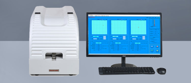
An ASTM D1434 oxygen permeability tester measures gas transmission using a pressure-based approach. Its result depends on a measurable pressure change across the specimen, so a small leak, an unstable temperature, or a test stopped before the appropriate measurement period can affect the outcome. Before treating two values as conflicting, confirm that they represent the same property and were obtained under comparable conditions.
Start by checking what the reported numbers represent
A difference between two reports is not always a repeatability problem. One may report a gas transmission rate for a specimen of a particular thickness, while another reports permeability calculated using thickness and pressure difference. The units, exposed area, pressure basis, and calculation settings must match before the values can be compared.
Thickness normalization also needs care. For a reasonably uniform, homogeneous film, permeability can be calculated from transmission and thickness under the applicable method. A multilayer structure, coating, or film with an uneven barrier layer may not behave as though its barrier performance changes in direct proportion to total thickness. Do not use a thickness-normalized value to dismiss a real difference between structures.
Check the applicable edition of ASTM D1434, the selected procedure, and the instrument instructions. Record the test gas, temperature, pressure conditions, specimen conditioning, exposed area, and calculation basis. ASTM D1434 covers gas transmission measurement by pressure-based procedures; it should not be assumed to be interchangeable with an oxygen-specific sensor method simply because both reports concern oxygen barrier performance.
Use the direction of the change as a clue
The pattern of variation can help prioritize checks. It does not identify a cause on its own, but it can keep an investigation focused.
Preserve the original pressure-versus-time data when available. A final number alone may conceal an unstable baseline, a slow transition toward steady behavior, or an abrupt disturbance caused by a handling or supply issue.
Rule out leakage before adjusting the calculation
Leakage is a critical suspect when measured transmission seems unexpectedly high or changes substantially after remounting. Gas can bypass the intended exposed area through a damaged gasket, a wrinkle across the seal, contamination on a sealing surface, or an improperly assembled connection. On a high-barrier material, a small system leak can be significant relative to the gas passing through the film.
Follow the instrument manufacturer’s leak-check procedure using the specified blank or other suitable barrier. A blank-cell or system check helps assess the apparatus, but it does not automatically prove that a particular specimen is sealed correctly. If the blank check is acceptable and the result changes after the specimen is remounted, inspect the specimen edge and its contact with the seal.
- Clean the sealing surfaces using materials and procedures compatible with the cell and gasket.
- Inspect seals for damage, deformation, embedded particles, or residue. Replace components when the manufacturer’s criteria require it.
- Mount a fresh specimen without folds or tension that could distort it, and close the cell according to the prescribed procedure.
- Repeat the applicable leak or background check. Compare the trace and result with the earlier run before changing any other setting.
Do not subtract an assumed leak value merely to make a result agree with an earlier test. Any background correction must be supported by the applicable procedure and the instrument’s validated calculation. If the background is unstable or too large relative to the specimen signal, repair or further verification is needed before reporting a reliable material result.
Examine the specimen, not just the average thickness
Two pieces cut from the same roll or sheet can differ. Creases, pinholes, scratches, inclusions, and local coating defects may create a genuinely higher transmission path. Handling can introduce some of these defects, particularly when thin films are pulled tightly over a cell opening or cut against a rough surface.
Cut specimens with a clean tool and handle the test area as little as practical. Inspect both sides under suitable lighting, including the region that will contact the seal. Avoid using a damaged piece for a routine representative measurement unless the purpose is specifically to investigate defects. Keep track of where each specimen was taken; differences associated with a location may be a material or manufacturing issue rather than an instrument issue.
Measure thickness using an appropriate method for the material and the reporting procedure. Take measurements at representative positions without compressing a soft film excessively or measuring a folded edge. Record individual readings as well as the value used in the calculation. A single thickness measurement away from the exposed test area may not describe the portion through which gas is transmitted.
Also maintain specimen orientation. In a multilayer structure, placing the opposite surface toward the high-pressure side can change the transient response and may affect comparison when layers respond differently to moisture or gas exposure. Mark the sides before cutting if the construction is not visually obvious, and document the orientation rather than relying on memory.
Control the conditions that change the material response
Temperature and conditioning
Gas transport through polymer films is temperature-dependent. A change in cell or specimen temperature can therefore change the actual transmission, not merely the instrument reading. Temperature changes can also disturb the measured pressure. Compare the recorded temperature during the measurement period, not only the setpoint entered at the start.
Allow the cell and specimen to reach the required conditions before collecting the reportable measurement. Check for room drafts, nearby heat sources, and disturbances after the cell is opened. If the displayed temperature is stable but the pressure trace continues to drift, investigate both thermal equilibration and leakage rather than assuming the specimen is at fault.
Conditioning matters because some barrier materials are sensitive to moisture and storage history. A specimen taken directly from an open package may not be equivalent to one held under controlled conditions. Use the conditioning specified in the test plan, document deviations, and compare specimens with similar exposure histories. Do not assume that the humidity displayed in the room is the humidity at the specimen during the test; use the conditions established by the apparatus and procedure.
Pressure, gas, and test duration
Verify the gas identity and supply condition, the pressures on the appropriate sides of the specimen, and the pressure difference used in the calculation. A changed pressure setting can alter the driving force and may make two raw transmission readings incomparable. Confirm that the cell has been evacuated or otherwise prepared as required by the chosen procedure and instrument instructions.
Test duration deserves particular attention when switching materials. A thicker specimen or a material with slow gas transport may take longer to approach the measurement regime required by the method. Starting the calculation too early can produce a result influenced by the transient response rather than the intended transmission behavior. Conversely, an unexplained change late in a run may indicate temperature movement or system instability.
Review the pressure trace against the acceptance criteria in the applicable procedure. Do not apply a fixed waiting time borrowed from a different material as proof of steady state. When the required behavior is not reached, extend the observation only as permitted by the procedure and investigate whether the instrument’s range and background are suitable for that specimen.
Separate material variation from instrument variation
A practical investigation changes one factor at a time. Begin with a system check, then test multiple specimens prepared from the same material under the same conditions. Keep the procedure, gas, pressure settings, conditioning, and operator technique consistent. Document each mounting and retain the individual results rather than reporting only an average.
Then compare the sources of variation:
- Variation mainly after remounting: investigate sealing, specimen placement, and damage caused during handling.
- Variation among sampling locations: inspect local thickness and defects, and review whether the sampling plan represents the material.
- Variation across different materials: check whether the test duration, measurement range, and background are appropriate for each barrier level.
- Variation without an apparent specimen change: review pressure traces, environmental conditions, gas supply, instrument checks, and recent configuration changes.
A suitable reference material can help track system performance when used with defined conditions and an established comparison procedure. It is not a substitute for a leak check, and agreement on one reference does not guarantee accurate results for every thickness or transmission level. Use it alongside the instrument’s maintenance and calibration records.
Decide whether the result can be used
Do not reject a material or release it solely because one unexplained result crosses a specification limit. First verify the result against the applicable laboratory procedure: confirm calculations and units, inspect the run record, and determine whether there is evidence of a test invalidity. A retest should follow a documented rule; repeating measurements until one passes can conceal both material defects and equipment problems.
If repeated system checks fail, the pressure trace remains unstable, or the specimen signal cannot be distinguished adequately from the background, stop reporting numerical permeability results from that setup until the issue is resolved. Preserve the records and contact the equipment manufacturer or the laboratory’s responsible technical personnel with the test conditions, leak-check outcome, and pressure traces. Those details are more useful for diagnosis than the final permeability value alone.
Leave A Reply
Search by Keywords