




Recent Posts
 How Bone Screw Self-Tapping Testers Measure Axial Force and Tapping TorqueOct 17, 2026
 ASTM F543 Bone Screw Pull-Out Testing: Setup and Reporting RequirementsOct 17, 2026
 What does a lipstick breaking strength tester actually measure?Oct 16, 2026
 What Does an Adhesive Tack Tester Measure in Pressure-Sensitive Tapes?Oct 15, 2026
 Which gases can a gas transmission rate tester actually measure?Oct 14, 2026
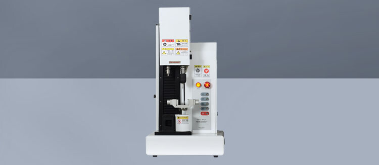


Yes, a thin film tensile tester can be compatible with ASTM D882 when its mechanical design, measurement system, software, and specimen handling support the test method's required conditions. Compatibility is not established by calling an instrument a “film tester” or by matching only its maximum load capacity. The tester must produce controlled tensile loading on thin plastic sheeting, record force and extension with suitable resolution, maintain the selected separation rate, and hold the specimen without slippage or premature grip damage.
ASTM D882 is used for determining tensile properties of thin plastic sheeting. The resulting values may include tensile strength, elongation, tensile modulus, yield behavior, and force at specified extension. Each value is affected by the test setup. A machine with accurate force measurement but unsuitable grips, poorly controlled speed, or an unreliable extension signal can still generate misleading results.
Force measurement must suit the film, not merely the machine frame
The load cell range is one of the first compatibility questions. Thin films often develop relatively low forces, especially when narrow strips, low-thickness materials, or extensible structures are tested. A very large load cell can physically complete the test, yet provide weak resolution near the actual force range. Small changes in yield force, peak force, or low-strain modulus then become harder to distinguish from measurement noise.
A suitable tester should accept load cells selected for the expected specimen force while retaining adequate overload protection. The useful range should be evaluated against the material's width, thickness, expected tensile strength, and test direction. A multilayer barrier film, a stretch film, and a thin oriented polypropylene film may have substantially different force profiles even when their nominal thicknesses appear similar.
Force accuracy also needs to remain valid through the range in which data are reported. Peak force may occur well above the force used for modulus calculations. If the force signal is stable only near the upper end of the range, the modulus region can be distorted. Conversely, selecting an extremely low-capacity load cell for a film that occasionally breaks at a high local-force point creates overload risk and interrupts repeatability.
Crosshead speed requires real control and verification
ASTM D882 testing uses a specified rate of grip separation. The selected speed influences viscoelastic films strongly: a slower pull can allow molecular relaxation, while a faster pull can raise apparent stress, change yield behavior, and reduce measured elongation before break. Two reports cannot be meaningfully compared when the test rates differ, even if the samples came from the same material roll.
The tester therefore needs a drive system that can reach, hold, and reproduce the required separation speed over the full test. This includes the low-speed behavior sometimes needed for thin, highly extensible materials. Software settings alone are insufficient if the actual moving-grip speed drifts during acceleration, changes under load, or is not verified as part of equipment calibration.
Acceleration deserves attention because short gauge lengths and low elongation at break can leave little steady-state travel before failure. If a specimen breaks during the speed ramp, part of the curve reflects acceleration rather than the selected test condition. The system should allow the test sequence to establish the specified motion before the force-extension data used for calculation are acquired, where the chosen procedure requires it.
Grip separation and extension are related, but they are not interchangeable
A thin film tester must measure the movement between grips accurately enough for the selected gauge length and elongation range. Crosshead displacement is commonly used as the extension source, particularly where grip separation is the intended basis of the test. Its reliability depends on frame stiffness, drive backlash, grip seating, and slip control. Any movement not occurring within the gauge section can appear as specimen extension.
This distinction becomes especially important for tensile modulus. Modulus is calculated from the early portion of the stress-strain curve, where extension is small. A slight seating movement in a grip, a specimen that straightens after loading begins, or compliance in the load train can flatten the initial slope and understate modulus. High-elongation materials create a different problem: crosshead travel must be sufficient to capture break without reaching the travel limit first.
Where an extensometer or video-based strain measurement is used, its suitability must be assessed against thin-film behavior. Contact devices can mark, load, or damage delicate specimens. Non-contact measurement avoids physical contact but requires stable contrast, valid gauge marks, appropriate tracking settings, and a clear view of the gauge section throughout deformation. The reported strain method should be consistent across comparative work because extension source changes can alter the result.
Grips determine whether the test represents the material
Grip selection is often the practical boundary between a valid ASTM D882 setup and a visibly poor test. The specimen should fail in the gauge section, not slide from the jaws, tear at a sharp grip edge, or neck because the clamping pressure crushed a weak film. A broken specimen near a grip is not automatically invalid, but repeated edge failures call for investigation before the data are accepted.
Mechanical grips with suitable faces are common, but the face texture, clamping pressure, jaw alignment, and specimen thickness all matter. Serrated faces can prevent slip in some films yet initiate damage in thin, brittle, coated, or metallized structures. Smooth rubber-faced grips can distribute pressure more gently, although they may permit slip on low-friction surfaces. Pneumatic grips offer more repeatable clamping force than manual tightening when grip pressure is controlled and appropriate for the material.
Thin films frequently show apparent grip problems that are actually specimen-preparation problems. A strip cut with a nicked edge may tear at the grip even when the grip itself is suitable. Uneven width changes calculated stress because stress is based on the original cross-sectional area. Curled samples may enter the grips under residual bending, creating an irregular initial portion of the curve. Good fixtures cannot fully correct poor specimen geometry.
- Grip faces should cover enough specimen width to prevent local pull-out while leaving a defined, unobstructed gauge section.
- Alignment should keep the tensile axis centered through the specimen. Off-axis loading can make one edge carry force earlier than the other.
- Clamping conditions need to be repeatable. Changing jaw pressure between specimens can change both slippage and the location of failure.
- For delicate, very thin, or difficult-to-hold films, tabs or an alternative gripping arrangement may be justified only when documented and consistent with the applicable procedure.
Specimen geometry and material direction must be entered correctly
The tester software needs the fields and calculation capability required by the chosen ASTM D882 procedure. At minimum, this normally includes specimen width, thickness, initial gauge length, test speed, and the force or extension criteria used for reported properties. Stress cannot be calculated correctly from force alone. For thin plastic sheeting, the original cross-sectional area is derived from specimen width and thickness, so both inputs affect tensile strength and modulus.
Thickness is a frequent source of disagreement between otherwise competent tensile tests. A single thickness reading is rarely representative of a film with gauge variation, coating layers, embossing, or local orientation differences. Thickness measurement locations, instrument condition, and averaging rules should follow the applicable procedure. The tensile tester cannot repair an incorrect thickness value after the test is complete.
Film direction must also be identified. Machine direction and transverse direction can exhibit different strength, elongation, yield, and modulus because extrusion, casting, blowing, stretching, winding tension, and lamination affect molecular orientation. A report that lists a tensile value without direction is incomplete when directionality matters. The test record should preserve the relationship between each specimen and the source sheet or roll.
Data acquisition must capture the actual curve shape
ASTM D882 results are derived from a force-extension or stress-strain curve, not from a single peak reading. The acquisition rate must be sufficient to capture relevant changes in the material response. A brittle, oriented film can fail rapidly after reaching maximum force. A low acquisition rate may miss the true peak or obscure the point used for yield determination. For a ductile film, inadequate sampling can smooth a yield plateau or make a force-at-extension calculation less reliable.
The software should retain raw or appropriately resolved test data, show the curve, and calculate the selected properties from traceable inputs. It should distinguish between test termination caused by specimen break, a travel limit, overload, emergency stop, or a manually ended run. Treating every stopped test as a break can place invalid results into an average.
Automatic break detection is useful only when its threshold is appropriate for the material. Films with long post-yield drawing behavior can show large force changes before final separation. A threshold set too high may end the run before the intended endpoint. One set too low may fail to recognize break promptly, causing the grips to continue separating after failure. The method configuration should define the event logic rather than leaving it to a generic factory setting.
Modulus and yield settings need explicit definitions
“Modulus” is often treated as a simple output, but the calculated value depends on the specified strain interval and extension measurement basis. The early curve can include slack removal, specimen alignment, grip seating, and initial material response. A tester that offers a generic tangent modulus without allowing the required calculation range may not support a directly comparable ASTM D882 result.
Yield can also be ambiguous. Some films show a distinct maximum followed by lower drawing force. Others have a gradual transition without a clear peak, and some brittle films break before recognizable yield. The analysis method should be selected according to the applicable procedure and material behavior. Forcing an automatic yield value onto every curve creates a number, but not necessarily a meaningful property.
Environmental control may be part of a valid comparison
Film tensile behavior is sensitive to conditioning. Moisture-sensitive materials, plasticized structures, and some barrier laminates can change response after exposure to different temperature or humidity conditions. Even when the tester itself is accurate, comparing specimens conditioned differently can lead to false conclusions about material variation.
A compatible test system should therefore permit the required conditioning and test environment to be recorded with the result. Where testing must occur under controlled conditions, the equipment arrangement needs sufficient stability for the grips, load cell, and extension measurement system. Temperature exposure can also alter grip friction and pneumatic behavior, so a fixture that performs well at room conditions should not be assumed suitable in every environment.
Calibration is broader than the load cell certificate
Force calibration is essential, yet ASTM D882 readiness also relies on verification of speed, displacement, gauge length, grip alignment, and data calculations. A current force certificate does not confirm that the moving grip travels at the selected rate or that the reported strain matches actual grip separation. Software changes, replacement grips, a new load cell, and modified test templates can all affect the testing chain.
Routine review should include representative curves, failure locations, zero stability, and repeatability of grip setup. Sudden changes in elongation with stable tensile strength often point toward slip, gauge-length entry errors, or extension-measurement changes rather than a real material shift. A fall in modulus with little change in peak force may indicate slack, compliance, or a changed calculation interval. Looking at the curve before releasing results is more informative than reviewing only the final averages.
Questions that affect ASTM D882 compatibility
Is a universal testing machine automatically suitable for thin films?
No. A universal frame may have adequate force capacity, but ASTM D882 work still requires suitable low-force measurement, speed control, travel, grips, extension handling, and calculation settings. The frame is only one part of the test system.
Can crosshead displacement be used for elongation?
It can be used when it matches the selected procedure and the grip system is stable. Its limitations should be recognized, particularly for low-strain modulus measurements or specimens prone to grip seating and slip.
Why do specimens repeatedly break at the jaws?
The cause may be excessive clamping pressure, aggressive grip faces, jaw misalignment, poor strip cutting, damaged specimen edges, or a material weakness introduced during gripping. Changing the grip type without examining the specimen and alignment can leave the underlying cause unresolved.
Can results from different gauge lengths be compared?
Not without care. Gauge length affects measured elongation and may influence deformation behavior, especially for films with localized necking or defects. The gauge length should be reported and held constant when results are compared.
A thin film tester supports ASTM D882 when it controls the intended tensile conditions and produces traceable measurements that represent deformation within the specimen gauge section. The most reliable setup is the one in which load range, grips, speed, extension method, specimen dimensions, and calculation rules are selected as a connected system rather than as separate instrument options.
Leave A Reply
Search by Keywords