




Recent Posts
 ASTM D642 and ISO 12048: Requirements for Package Compression TestingOct 12, 2026
 What Does a Paper Thickness Tester Measure, and Why Does It Matter in QC?Oct 12, 2026
 How test speed affects lipstick breaking strength resultsOct 10, 2026
 Choosing a Water Vapor Transmission Rate Tester for flexible filmsOct 10, 2026
 How to select a friction peel tester for flexible packaging filmsOct 09, 2026

A rigidity result that changes noticeably from one operator to another can create an uncomfortable situation in a quality laboratory. The same lot of needle tubes may appear acceptable in the morning and questionable in the afternoon, even though the material has not changed. It is tempting to blame the instrument, especially when the difference is small but persistent. In practice, however, operator-to-operator drift usually develops through a chain of seemingly minor variations: how the tube is supported, where the load is applied, how the sample is handled, whether the test speed is truly consistent, and even how the result is reviewed.
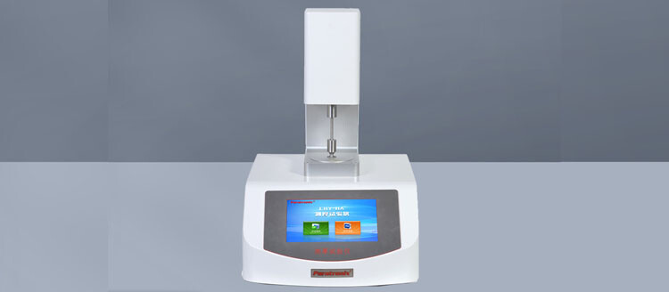
A Needle tube rigidity tester is designed to turn a controlled bending action into a measurable force or rigidity value. It provides the structure needed for repeatable testing, but it cannot fully compensate for an undefined workflow. When several people use the same tester, the laboratory needs more than a correct instrument setting. It needs a shared testing language: the same sample condition, the same positioning logic, the same parameter control, and the same response when something looks unusual.
This matters in pharmaceutical packaging, medical-device components, and precision metal tubing, where needle tube stiffness can influence downstream assembly, user handling, penetration performance, and product consistency. A result should represent the needle tube—not the individual habits of the person running the test.
Why the same needle tube can produce different rigidity readings
Rigidity testing is sensitive because it is fundamentally a bending measurement. The measured force depends not only on the tube’s material and dimensions, but also on the geometry of the test arrangement. A small shift in the distance between supports or loading point can alter the bending response. If one operator positions the tube at the exact reference mark while another positions it by eye, the two results may not be directly comparable.
In many laboratories, variation enters before the sample is even placed on the fixture. One operator may take tubes directly from the production area, while another allows them to rest in the test room. One may test samples with protective sleeves or packaging residue removed carefully; another may bend or scratch a tube during unpacking without realizing it. These differences are easy to dismiss because the tube looks unchanged. Yet a thin-walled cannula can be affected by prior deformation, surface contact, or temperature-related material behavior.
The recurring causes of operator drift generally fall into four connected areas:
- Sample condition: differences in handling, conditioning, identification, orientation, or prior damage.
- Fixture setup: inconsistent support span, seating depth, loading position, or alignment.
- Test method execution: changes in speed, target displacement, preload, return settings, or start-point selection.
- Data judgment: inconsistent treatment of unstable curves, outliers, failed runs, or repeat tests.
The important point is that these factors often overlap. A slight positioning error may be insignificant in one test but become visible when combined with a marginally bent sample and an operator who starts the test before the specimen is fully settled. This is why repeatability problems can feel frustratingly unpredictable.
The fixture is not just a holder
For a needle tube rigidity test, the fixture defines the mechanical boundary conditions. It determines where the sample is supported, where the force is applied, and how freely the tube can bend. If the fixture is dirty, worn, misaligned, or used differently by different people, the tester may deliver stable force measurement while the test itself remains unstable.
Start by examining the parts operators touch most often. Are the supports clearly marked? Is there a physical stop or guide that makes the support span repeatable? Does the loading probe contact the intended location every time? Can a tube roll, shift sideways, or sit at an angle before the test begins? If the answer to any of these questions is yes, the process relies too heavily on operator judgement.
A robust setup should make the correct placement easy and the incorrect placement obvious. Visual reference lines, fixed locating features, defined clamping rules where appropriate, and a documented sample orientation all reduce freedom for unintended variation. For very small-diameter tubes, magnification or a camera-assisted positioning approach may be justified, particularly when the test method requires a precise loading location.
Operators should also inspect the contact surfaces routinely. Dust, metal particles, lubricant traces, adhesive residue, or fragments from previous samples can change how the tube rests on the supports. A tube that is not seated consistently may show a force curve that looks noisy, delayed, or unexpectedly high. Cleaning should therefore be part of the method, not an optional housekeeping task performed only when a problem becomes visible.
Parameter drift can hide behind “standard” settings
Most operators understand that test speed and displacement matter. What is less obvious is how easily the effective settings can change when a method is edited, copied, or manually rebuilt. A test speed that is close to the intended value may still produce a different response, especially where the material exhibits time-dependent behavior or where the system settles differently at the beginning of movement.
Review the active method rather than assuming it is correct. Confirm the following points at the start of each shift or test campaign:
- crosshead or probe travel speed;
- specified bending displacement or force endpoint;
- support span and loading geometry;
- preload or contact-detection setting, if used;
- data acquisition and calculation settings;
- return travel and fixture clearance;
- sample identification and result export fields.
A common source of confusion is the zero point. Some operators zero the force channel before placing the sample; others do so after the specimen is positioned. Neither approach is automatically correct unless it is defined in the approved procedure and supported by the instrument method. If the tube is already touching the probe, under slight stress, or held unevenly when zeroing occurs, the test can begin with a biased baseline.
The same concern applies to contact detection. If the instrument begins recording meaningful load at different physical points between runs, the force-versus-displacement curve may be shifted. That shift can affect a calculated rigidity value, depending on the method. Operators need a clear rule for what “contact” means and how to recognize when contact detection has failed.
Sample handling often explains the “mystery” variation
Needle tubes are slender components. They should not be treated like bulk metal coupons that can be picked up, moved, and repositioned repeatedly without consequence. A slight bend introduced during removal from a tray may not be obvious until the tube is placed on the tester. The first test then becomes a measurement of both inherent rigidity and accidental pre-deformation.
Use handling tools and practices that suit the component. Clean forceps, soft-jaw tools, gloves where required by the product and laboratory procedure, and dedicated sample trays can reduce incidental damage. Avoid touching the defined bending region whenever possible. If tubes have bevels, hubs, protective caps, coatings, or other assembly features, the procedure should state exactly which portion is tested and how the component is oriented.
Conditioning deserves equal attention. If samples move between a warm production floor, a warehouse, and a controlled laboratory, allow sufficient time for them to reach the specified environment before testing. Even when the tube itself is metallic, attached polymer elements, lubricious coatings, residual processing materials, and fixture contact conditions may respond differently at different temperatures or humidity levels. The goal is not to create an idealized laboratory ritual; it is to ensure that every operator tests under comparable conditions.
Watch the curve, not only the final number
A single reported value is useful for release decisions, but the force-displacement curve often reveals the reason behind drift. Operators should be trained to recognize the difference between a normal curve and a suspicious one.
A smooth, progressive increase in force generally suggests stable contact and bending. Sudden steps may indicate slipping, a fixture shift, or a change in contact condition. Early spikes can arise from an incorrectly seated tube, probe impact, or an unsuitable preload setting. A curve that begins unusually high may point to pre-stress, incorrect zeroing, or a sample already touching the loading point before the test starts.
This does not mean every unusual curve should be discarded. Rejection without a defined rule can become another source of operator variation. Instead, laboratories should establish criteria for invalid runs. For example, a test may require review when the curve shows visible slippage, when the sample moves out of the fixture, when the probe misses the defined contact area, or when a documented equipment fault occurs. A result should not be repeated simply because it is inconvenient or outside expectations.
Keeping the original curve with the result provides a useful audit trail. Over time, curve review can reveal patterns that a spreadsheet of final numbers may conceal: one fixture station that causes instability, one operator who uses a different seating technique, or one sample batch with handling damage.
Build an operating procedure people can actually follow
A procedure becomes effective when it translates a technical method into visible actions. “Position sample correctly” is not enough. An operator needs to know where the tube reference point should sit, which direction the bevel faces, whether the tube may be rotated, how to confirm that both supports are engaged, and what to do if the sample slips.
For a Needle tube rigidity tester, a practical operating sequence may include the following:
- Verify instrument readiness, fixture cleanliness, and current calibration status.
- Open the approved test method and confirm that the displayed parameters match the controlled version.
- Check the sample ID, quantity, conditioning status, and required test orientation.
- Place the needle tube using the defined locator or reference mark; do not force it into position.
- Confirm alignment from the designated viewing angle before starting the test.
- Run the test without touching the fixture or bench during measurement.
- Review the force curve and result against documented validity rules.
- Record any abnormal observation immediately, including repositioning or equipment-related events.
Short visual work instructions near the instrument can be more valuable than a long procedure stored in a digital folder. A photograph or diagram is often helpful in an internal SOP, but even without it, a concise setup checklist can prevent drift during busy shifts, staff changes, or production investigations.
Calibration confirms the instrument; verification confirms the daily process
Formal calibration is essential, but calibration alone does not prove that the complete test setup is under control. Calibration typically addresses the performance of the force measurement and motion system according to the laboratory’s quality program. Daily or periodic verification addresses a different question: is the tester, fixture, method, and operator workflow behaving consistently today?
A suitable verification practice may include checking zero stability, confirming travel movement, inspecting fixture condition, and using an approved reference device or control sample where the laboratory has established one. The exact approach should reflect the applicable method, internal quality system, and risk level of the product being tested.
If verification results begin to trend, do not wait for a full failure. A gradual change may indicate probe wear, loosening hardware, contamination, software setting changes, or an emerging operator technique issue. Trend charts are especially useful when multiple shifts share the same equipment. They turn a vague complaint—“the readings feel different lately”—into evidence that can be investigated.
Use a small measurement study before changing specifications
When rigidity results vary between operators, it is risky to adjust product limits before understanding the measurement system. The product may be stable while the measurement method is not. Before escalating to a manufacturing issue, conduct a focused repeatability and reproducibility review.
Select representative samples covering the normal range of rigidity, then have multiple trained operators test them using the same approved method. Keep the equipment, fixture, environmental conditions, and sample handling instructions controlled. Compare variation within each operator’s repeated tests and variation between operators. Record observations, not just numbers: Was the sample difficult to place? Did one person use a different orientation? Did one run show fixture movement?
The study does not need to become a complicated statistical exercise to be useful. Its first purpose is diagnostic. If one operator’s repeated results are scattered, focus on technique, seating, or method interpretation. If every operator is individually consistent but their averages differ, look for systematic differences in setup or sample orientation. If all results fluctuate, inspect the instrument, fixture, sample condition, and environment.
When to suspect the tester itself
Operator drift should not become an excuse to overlook equipment problems. Suspect the tester or fixture when differences persist despite controlled samples and a tightly followed procedure; when force curves show recurring noise or irregular movement; when zero does not remain stable; when the loading probe is visibly damaged or misaligned; or when verification checks show a trend.
At that point, pause routine testing if required by the quality procedure and inspect the system systematically. Confirm mechanical fasteners, probe condition, support geometry, motion smoothness, software method integrity, and force sensor response. Service support may be appropriate when the issue cannot be resolved through documented checks.
As a manufacturer focused on packaging testing solutions for pharmaceutical packaging, plastic packaging materials, and high-barrier materials, Paratronix Instruments understands that reliable data comes from the combined performance of the tester, fixture, method, and people using them. The most useful support conversation begins with records: the active method, recent verification history, representative curves, fixture photographs, and a description of how results differ between operators.
Consistency is a daily discipline, not a one-time adjustment
The best control for operator-to-operator drift is not more complicated testing. It is a process that removes avoidable choices. Define the sample condition. Make positioning repeatable. Lock critical parameters. Train operators to read the curve as well as the final value. Verify the complete setup regularly, and investigate trends before they become quality disputes.
A well-managed Needle tube rigidity tester gives operators a dependable basis for evaluating bending performance. When the surrounding workflow is equally disciplined, rigidity results become easier to compare across shifts, people, lots, and time. That confidence is what allows a laboratory to make decisions based on the product’s real behavior rather than the accidental variation of the test process.
Leave A Reply
Search by Keywords